
Sintering Furnace Temperature Control Guide
A sintering cycle can follow the recipe exactly and still deliver a tray of parts that are warped, chalky, or a shade darker than the batch before it. The furnace did what it was told. The problem usually sits somewhere between the setpoint and the part: in the heating ramp, the way the load was stacked, the atmosphere inside the chamber, or the quiet assumption that one thermocouple speaks for the whole hot zone.
Sintering is a diffusion process, and diffusion is sensitive to time, temperature, and local conditions in ways that a single setpoint cannot capture. What follows breaks the cycle down in the order it acts on the part, then shows how to read a furnace specification against those variables, using the T-Bright Plus Sintering Furnace from Changsha Tianchuang Powder Technology Co., Ltd (TENCAN) as a working reference.
What Sintering Does to a Powder Compact
A pressed or cast powder body leaves forming with roughly half of its volume occupied by particles and the rest by pores. Sintering removes most of that porosity without melting the material. The driving force is surface energy: fine particles and curved necks carry excess energy, and at elevated temperature atoms migrate to lower that energy by building necks, rounding pores, and pulling particle centers closer together.
Because the mechanism is diffusion rather than flow, the compact shrinks. For many technical ceramics, linear shrinkage across a full cycle falls somewhere in the range of 15–20%, but the actual figure depends on powder grade, particle size distribution, pressing density, binder content, and the time–temperature schedule applied. That dependence is why shrinkage is a process output rather than a fixed material constant, and why two suppliers running the same nominal recipe can end up with different fired dimensions.
The three stages that decide the outcome
In the initial stage, particles form contact necks and the compact gains strength with very little dimensional change. In the intermediate stage, pores become smoother and interconnected channels close; this is where most of the density is gained and most of the shrinkage happens. In the final stage, the remaining porosity is isolated at grain boundaries and inside grains, and further densification competes directly with grain growth. Pushing the final stage too hard buys a little more density at the cost of coarser grains, which can degrade strength, translucency, or electrical properties depending on the material.
What sintering cannot fix
A sintering furnace cannot correct a density gradient created during pressing, nor can it remove binder that was never given a chance to escape. Laminations from poor powder filling, hard spots from uneven moisture, and density variation across a large compact all survive the firing cycle and often amplify during shrinkage. When a defect appears after firing, it is worth asking whether the furnace caused it or merely revealed it.
Heating Rate: Where Most Cycles Are Won or Lost
Heating rate controls how much temperature difference exists inside a part at any moment. A 20 mm thick ceramic section heated at 10 °C/min will be significantly hotter on its surface than at its core; the surface tries to shrink first while the core holds it back. The resulting stress either relaxes harmlessly, or it nucleates a crack that only becomes visible after cooling. Thicker sections, larger loads, and parts with sudden changes in cross-section tolerate far less ramp rate than thin coupons.
There is also a floor to heating rate. Ramping very slowly through the entire cycle is safe but unproductive, ties up the furnace, and can extend grain growth at intermediate temperatures. The practical target is the fastest ramp the part and the furnace can both accept, with deliberate slow segments where the physics demands them.
Binder removal is a separate problem
Organic binders, lubricants, and dispersants burn out well below sintering temperature, commonly in the 200–600 °C window depending on chemistry. This stage is governed by diffusion of decomposition products out of the compact, not by heat transfer, so it is usually the slowest part of the ramp: fractions of a degree per minute in some schedules, a few degrees per minute in others. Ramping through the burnout window too quickly traps gas inside the body, producing blisters, internal voids, or carbon residue that later interferes with densification and discolors the fired part.
Burnout also loads the chamber. Decomposition products must be swept away by airflow or atmosphere flow, and a furnace with a crowded load and weak exchange can hold those species near the parts longer than expected. In many shops, the fix is not a longer hold at temperature but a slower ramp plus better gas exchange through the hot zone.
Thermal gradients between the tray and the part
A control thermocouple reports the temperature at one point, frequently near a heating element or in a protection tube. The parts sit somewhere else, on setters with their own thermal mass, inside a chamber with its own circulation pattern. During a fast ramp, the gap between the reported temperature and the actual part temperature can be tens of degrees; during a hold, it closes. This is why a cycle that behaves well in an empty furnace may behave differently when the chamber is fully loaded, and why ramp rates should always be validated with the real load geometry.
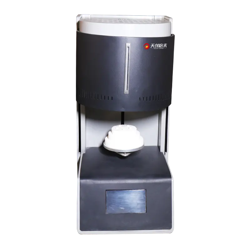
The T-Bright Plus Sintering Furnace. Chamber size, element type, and control configuration should be confirmed against the published specification for the model being considered.
Hold Temperature, Soak Time, and the Densification Window
Hold temperature is the single strongest lever on final density, which is precisely why it deserves more caution than it usually gets. Densification and grain growth share the same thermal activation, so any increase in temperature accelerates both. A small upward adjustment that solves a density problem can simultaneously push grain size past the point where strength or optical performance is acceptable.
Soak time works in the same direction but with diminishing returns. Early in the hold, density rises quickly; later, the curve flattens while grain growth continues steadily. The practical soak is the point where density has essentially plateaued. Holding beyond that point adds energy cost and microstructural damage without adding value.
For many oxide ceramics, sintering temperatures fall in the 1,200–1,600 °C range, but this is a broad generalization. Refractory carbides, transparent ceramics, and copper-based systems sit in very different windows, and every material supplier publishes a recommended schedule that should be treated as the starting point rather than the final answer.
Run a step test instead of guessing
When a cycle needs adjustment, one variable at a time is faster than intuition. A workable sequence looks like this:
- Fire three to five identical coupons at the current hold temperature with soak times spaced apart, for example 1 h, 2 h, and 4 h.
- Measure bulk density, linear shrinkage, and fired dimensions for each coupon, and record the values against the schedule that produced them.
- Repeat at a temperature 25–50 °C above and below the current setpoint, keeping soak time constant.
- Section one sample from each condition and inspect grain size and pore morphology, not just density.
Four to six firings usually define the window well enough to set production limits. The data also becomes the baseline for judging whether a later drift is a material change or a furnace change.
Cooling, Uniformity, and Load Practice
Cooling is where residual stress is set. A part that densified perfectly can still crack, warp, or develop surface flaws if it is pulled through a phase transformation or a steep thermal gradient too quickly. Thick sections and assemblies of mixed materials are the most exposed, because their components contract at different rates. Controlled cooling at a few degrees per minute through the sensitive interval, followed by faster cooling below it, is a common compromise; the exact interval depends on the material and should come from the supplier's data or from a cooling-rate study on real parts.
Temperature uniformity deserves equal attention. Manufacturers typically quote a uniformity figure measured in an empty or lightly loaded chamber at a specified temperature. Under load, that figure is optimistic. Heating elements radiate to the nearest surfaces, so parts near a wall or element run hotter than parts in the center; dense setters absorb heat and slow the response of whatever sits on them; and a chamber packed edge to edge restricts circulation. The result is a batch with a density gradient from the outside in, which often shows up as dimensional scatter rather than an obvious defect.
Setters, crucibles, and the crowded chamber
Every item placed in the furnace becomes part of the thermal system. Setters and saggers should be flat, stable at temperature, and consistent from run to run; changing setter material changes the cycle. Parts should be spaced to allow radiation and gas exchange, kept away from element walls and door edges, and positioned in the zone the furnace was actually surveyed in. Where a furnace offers multiple control zones, the load plan should respect them rather than treating the chamber as a single uniform box.
Recording the load arrangement alongside the cycle data costs a minute and saves hours later. When a batch fails, the first useful question is usually whether it was placed the same way as the batch that passed.
Atmosphere, Contamination, and Part Appearance
Atmosphere determines what the surface of the part reacts with. Air is adequate for many oxide ceramics; inert gas or vacuum is required where oxidation, residual carbon, or nitrogen pick-up would damage the material. The choice is not only about chemistry at the hold temperature. During burnout, the chamber is full of reactive organic fragments, and during cooling, the part is still hot enough to oxidize or absorb species if the atmosphere is switched or the chamber is opened early.
Contamination usually comes from three places: the heating elements and insulation, the setters and crucibles, and the parts themselves. Refractory insulation that has absorbed prior batches can release species for a long time, which is one reason a furnace that ran a colored or doped material should not be used for a clean one without a conditioning run. Crucibles should be dedicated to a material family. Elements and fixtures degrade, and their degradation products end up on the work.
Discoloration is often the first visible symptom and the least diagnostic. A gray or yellow tint may point to carbon residue from incomplete burnout, to oxidation during cooling, or to volatilization from a fixture. The fastest way to separate these is a controlled comparison: fire one clean part with no other load and fresh setters. If the discoloration disappears, the furnace atmosphere is fine and the problem lives in the load or the binder.
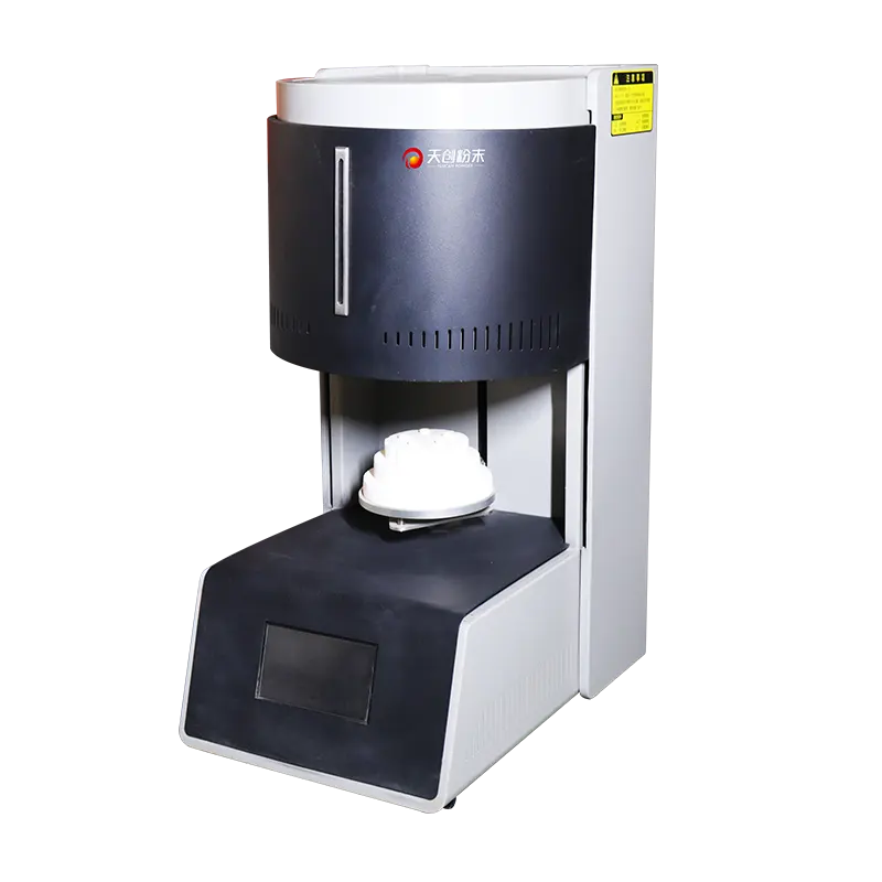
Configuration details vary between models. Atmosphere capability, element type, and zone control should be matched to the material being fired.
Reading a Sintering Furnace Specification Against Your Process
Furnace datasheets tend to list maximum temperature first, and buyers tend to read it first. The more useful number is the continuous working temperature at which the heating elements and insulation have an acceptable service life, because running at the absolute maximum shortens element life and increases maintenance cost. A furnace rated well above the intended process temperature leaves headroom for element aging and for occasional higher-temperature work; one rated exactly at the process temperature leaves none.
Beyond the temperature rating, five specification areas map directly onto the process variables discussed above:
- Chamber volume and usable dimensions — the space available after accounting for setters, fixtures, and clearance from elements, not the gross internal volume.
- Uniformity and zone control — how the figure was measured, at what temperature, and with what load; whether multiple control zones allow the profile to be tuned.
- Controlled ramp and cooling capability — whether the controller can execute the slow segments that burnout and cooling require, and whether cooling is passive or actively managed.
- Atmosphere and gas management — inlet and exhaust arrangement, sealing, and whether the configuration suits the material chemistry.
- Instrumentation and records — thermocouple type and location, over-temperature protection, and data logging adequate for traceability.
A platform such as the T-Bright Plus sintering furnace should be evaluated against the actual cycle rather than against a generic checklist: the profile you intend to run, the largest and thickest part you intend to fire, and the atmosphere you intend to use. Those three inputs narrow the field faster than any comparison table.
Questions worth asking before purchase
Ask how uniformity was measured and whether the manufacturer can supply the survey data. Ask what consumables the furnace needs, how often elements and thermocouples are expected to be replaced, and what the lead time is on those parts. Ask whether the controller supports multi-segment programs with hold steps and controlled cooling, and whether programs can be locked to prevent unauthorized edits on the shop floor. Ask about utility requirements, exhaust routing, and heat rejection into the room, since these often determine where the furnace can physically be installed.
Finally, ask what happens during a power interruption. A furnace that cools uncontrolled from 1,400 °C can ruin a load and stress its own elements; a controller that holds the chamber safely or restarts a defined segment is worth real money in scrap avoidance.
Common Defects and What They Usually Point To
Defect patterns are more informative than defect descriptions. The table below links the most frequent post-firing symptoms to the process area most likely responsible, with the first check that usually settles the question.
| Symptom | Likely cause | First check |
|---|---|---|
| Warping or sagging | Overfiring, uneven support, or a setter that softened | Compare fired density with the target and inspect setter flatness |
| Cracks after cooling | Ramp or cooling rate too fast for the section thickness | Halve the heating and cooling rates through the sensitive interval and repeat |
| Low density, chalky surface | Hold temperature or soak time insufficient; contamination | Fire a coupon at +25 °C with the same soak and measure density |
| Blisters or internal voids | Binder burnout too fast or poor gas exchange | Slow the ramp through the burnout window and reduce load density |
| Discoloration | Carbon residue, oxidation during cooling, or fixture volatiles | Fire one part alone with clean setters |
| Dimensional scatter across a batch | Non-uniform chamber temperature or uneven loading | Run a loaded-chamber survey with thermocouples at several positions |
| Exaggerated grain growth | Hold temperature too high or soak far beyond the plateau | Shorten soak and re-check density before lowering temperature |
Two or three symptoms appearing together narrows the diagnosis further. Warping plus exaggerated grain growth points to overfiring; warping plus normal density points to support and loading practice; low density plus discoloration points to atmosphere and contamination rather than to the schedule.
Validation, Maintenance, and Matching the Furnace to the Part
A sintering furnace drifts slowly. Thermocouples age, elements change resistance as they degrade, insulation absorbs contaminants, and door seals compress. None of this announces itself; it appears as a batch that is slightly off, then another. A scheduled routine catches the drift before it reaches production:
- Survey the chamber under a representative load at least annually, and after any element or thermocouple replacement.
- Track element resistance and power draw per segment; a rising trend predicts failure before it happens.
- Calibrate the control thermocouple on a fixed interval and keep the certificate with the furnace records.
- Inspect insulation, seals, and fixtures for contamination and mechanical damage at every element service.
- Keep a log that pairs each batch with its cycle program, load arrangement, and measured results.
That log is what turns a furnace from a black box into a process instrument. It is also the fastest way to answer the question that arrives after every material change: did the powder change, or did the furnace?
Matching a furnace to a part is ultimately a question of margins. The chamber should be large enough to load without crowding, the temperature rating should sit above the working setpoint with room for element aging, the control system should be able to execute the slow segments that burnout and cooling demand, and the atmosphere configuration should suit the chemistry of the material rather than the convenience of the purchase. Where any of those margins is missing, the process will run at the edge of its capability, and edge-of-capability processes produce exactly the kind of intermittent, hard-to-explain defects that consume the most engineering time.
For laboratories and production teams working through those decisions, the TENCAN sintering furnace series is a reasonable place to compare configurations against a defined cycle. The productive conversation is not about which furnace reaches the highest number on a datasheet, but about which chamber, control architecture, and atmosphere arrangement can repeat the profile your material actually needs, batch after batch, with maintenance you can plan for.