
Hydraulic Single Axis Disperser Mixing Guide
High-viscosity dispersion rarely fails because a mixer lacks power. It fails because the flow pattern, blade, shaft position, formulation, and operating procedure do not match the rheology of the batch. A product that looks mixed at the surface may still contain unwetted powder, hard agglomerates, or stagnant zones near the vessel wall. The consequences appear later as color drift, inconsistent viscosity, poor adhesion, surface defects, sedimentation, or rejected batches.
A hydraulic single axis disperser is often shortlisted for these duties because it combines a single-shaft mixing head with a hydraulic lifting system and a heavy-duty frame. That combination can be practical for viscous pastes, filled systems, pigment concentrates, ceramic slips, adhesives, sealants, and similar formulations. The equipment type is useful, but the name alone does not define performance. The result depends on how the blade generates flow, how the vessel contains that flow, how the shaft is positioned, and how the operator controls the addition of solids.
Why High-Viscosity Dispersion Is Difficult
Viscosity is not a single fixed number. Many dispersions are shear thinning, thixotropic, or slightly dilatant. Their apparent viscosity changes with shear rate, time, temperature, and solids loading. A batch may flow easily near a moving blade and behave like a stiff gel a short distance away. This is why a machine can appear to be circulating material while regions of the vessel remain poorly mixed. The problem is not only viscosity itself. It is the combination of yield stress, poor bulk flow, and limited exchange between the high-shear zone and the rest of the batch.
In a high-viscosity batch, material near the blade may move rapidly while material near the wall or bottom remains nearly stationary. The boundary between these zones can become a dead zone where powder fails to wet out and agglomerates survive. Torque rises, temperature climbs, and the operator may respond by increasing speed. That response can make matters worse by creating a deep vortex, drawing air into the product, or adding heat without improving bulk circulation. A more effective approach is to examine the whole mixing system: blade type, blade diameter, immersion depth, vessel geometry, baffling, feed sequence, and rheology control.
Wetting, Deagglomeration, and Distribution Are Different Steps
Dispersion is often described as if it were one operation. In practice, it includes at least three related steps. Wetting replaces air on the powder surface with liquid. Deagglomeration breaks weak clusters and agglomerates into smaller units. Distribution spreads those units evenly through the vehicle. Each step has different requirements. Poor wetting can leave fisheyes or powder pockets even when the machine has enough shear to break down the agglomerates that were properly wetted. Good distribution cannot compensate for agglomerates that were never broken down.
- Unwetted powder often appears as lumps, fisheyes, or a grainy surface after film formation.
- Surviving agglomerates may show up as roughness, filter blockage, or inconsistent gloss.
- Poor bulk circulation can create color drift, viscosity variation, or sediment at the vessel bottom.
- Excessive air entrainment can produce foam, voids, low density, or unstable process times.
- Overheating can change rheology, activate additives too early, or damage heat-sensitive ingredients.
A useful diagnostic question is simple: is the problem located near the blade, near the vessel wall, at the surface, or at the bottom? The answer points to different causes. Surface foam suggests air entrainment and excessive vortexing. Wall deposits suggest poor bulk flow or insufficient baffling. Hard lumps that persist after long mixing may indicate poor wetting, an incompatible dispersant, or agglomerates that are too strong for the available shear stress. Understanding the failure mode prevents random changes to speed and formulation.
How a Hydraulic Single Axis Disperser Works
The machine is built around one rotating shaft. A motor and drive system turn the shaft, and the shaft carries a dispersing blade or mixing element into the product. The frame supports the drive and guides the shaft. In a hydraulic single axis disperser, a hydraulic system raises and lowers the shaft assembly. This lift is not the dispersion mechanism. It is a positioning and handling system that allows the blade to be placed at the required depth, raised for vessel changes, and moved clear for cleaning and maintenance. The dispersion itself comes from the interaction between the rotating blade, the product, and the vessel.
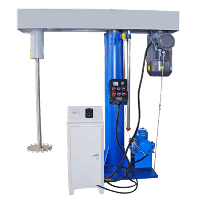
Hydraulic single axis disperser for high-viscosity mixing and dispersion.
The blade creates a combination of rotational flow, radial flow, axial flow, and localized shear. In a typical dispersing disc, the highest shear occurs near the blade tip and along the edges of the teeth. Material is accelerated outward, then circulates back toward the shaft. In a viscous batch, this circulation loop may be short and uneven unless the blade diameter, speed, and vessel geometry work together. The operator sees a rolling surface, but the important question is whether material is repeatedly passing through the high-shear zone and whether the lower part of the vessel is being renewed.
TENCAN, the brand of Changsha Tianchuang Powder Technology Co., Ltd, presents the hydraulic single axis disperser as a product for mixing and dispersion duties. As with any single-shaft machine, the practical result depends on the selected blade, vessel, speed range, and control arrangement. Buyers should confirm the offered configuration against their actual formulation rather than relying on a generic machine category. A machine that works well for a low-viscosity pigment concentrate may not be suitable for a highly filled paste with a high yield stress.
What the Single Shaft Does and Does Not Solve
A single shaft gives one clear flow pattern. That simplicity can be an advantage because the operator has fewer variables to control, and the vessel is easier to clean and inspect. It can also be a limitation. With one shaft, the machine cannot independently create two separate flow fields or combine high-shear dispersion with a slow sweeping motion unless the blade and vessel are designed to support that behavior. For very high-viscosity products, the bulk movement must often come from a large-diameter blade, an appropriate vessel wall, and a suitable baffle arrangement. A small high-speed disc alone may create good local shear but poor batch-level turnover.
This is why equipment selection should begin with the product, not the machine name. If the main problem is breaking down a pigment concentrate, the blade and tip speed may be central. If the main problem is moving a stiff paste with limited flow, the vessel and blade diameter may matter more. If the main problem is powder wetting, the feed point and addition rate may dominate. The single-shaft disperser can serve several of these duties, but it should be configured for the dominant duty. Otherwise, the machine may be technically capable of rotating while still failing to produce a uniform batch within a practical cycle time.
Hydraulic Lift and Shaft Position
The hydraulic lift affects the process because the blade must sit at a useful height in the vessel. If the blade is too high, it may only move the top layer, create a strong vortex, and leave the lower part of the batch undisturbed. If the blade is too low, it may scrape the bottom, create excessive drag, or fail to form a stable circulation loop. The correct position depends on the blade type, vessel shape, fill level, and product rheology. The lift makes it easier to adjust and repeat that position, which is valuable during process development.
The lift also has practical benefits. It can reduce the physical effort of moving a heavy shaft and drive assembly. It can provide clearance for changing vessels, adding solids, or cleaning. It can help the operator inspect the blade and shaft without dismantling the entire machine. These are not cosmetic features in a production environment. They influence changeover time, operator safety, and the consistency of repeated batches. The lift should therefore be evaluated as part of the working system, not as a separate selling point.
Blade, Speed, and Vessel Geometry
The blade is the main interface between the machine and the product. Different blade shapes create different balances of pumping, shear, and axial flow. A toothed dispersing disc is often used when high localized shear and deagglomeration are needed. A more open blade or paddle may provide better bulk movement in a viscous mass. A blade designed for one rheology may be inefficient in another. The best choice is not simply the blade with the highest shear. It is the blade that can wet the powder, break down the target agglomerates, and still maintain circulation throughout the batch.
Blade diameter has a strong effect on both flow and torque. A larger blade can move more material and may improve bulk circulation, but it also increases the load on the shaft and drive. A smaller blade can create high tip speed at a given rotational speed, but it may leave large stagnant regions in a viscous vessel. The relationship between blade diameter and vessel diameter is therefore an important design consideration. If the blade is very small relative to the vessel, the high-shear zone may be too localized. If it is very large, the machine may lose clearance and may not generate the intended shear pattern.
Tip Speed Is a Starting Point, Not a Recipe
Tip speed is often used to compare dispersing conditions. For a blade of diameter D, rotating at N revolutions per minute, the approximate tip speed in meters per second is V = p x D x N / 60, with D expressed in meters. This calculation is useful because a small blade at high rpm and a large blade at lower rpm can produce different flow and shear conditions even when their tip speeds are similar. Tip speed alone, however, does not define the process. The number of passes through the high-shear zone, the residence time, the blade tooth geometry, the vessel baffles, and the product rheology all affect the result.
A common mistake is to copy a tip speed from one application to another. A value that works for a low-viscosity dispersion may overheat or over-aerate a viscous paste. A value that provides good deagglomeration in a small vessel may not provide enough bulk flow in a larger vessel. The practical approach is to establish a safe operating window, then adjust speed while watching torque, temperature, surface behavior, and dispersion quality. If the vortex becomes deep, air entrainment rises, or the product climbs the shaft, the speed or blade position may need to change before the batch is damaged.
Immersion Depth, Vortex, and Baffles
Immersion depth changes both the flow pattern and the air entrainment risk. At shallow immersion, the blade may create a strong surface vortex and draw air into the product. At deeper immersion, the surface may be calmer, but the blade may not generate enough surface renewal for powder addition. The correct depth often changes during the batch. For example, the blade may start lower for initial wetting, then be raised or lowered as the batch viscosity develops. A hydraulic lift makes these adjustments easier, but the operator still needs a defined procedure so that each batch follows the same path.
Baffles and vessel shape help control swirling and direct the flow back toward the blade. In a round vessel with a centered shaft, the product can rotate like a solid body, reducing the relative motion between blade and fluid. Off-center positioning, wall scrapers, or baffles can interrupt that rotation. The right solution depends on the product and the machine configuration. A baffle that improves flow in one formulation may create dead zones or cleaning difficulties in another. For this reason, vessel geometry should be treated as part of the dispersion system, not as a simple container.
| Process variable | Main effect | What to check |
|---|---|---|
| Blade type | Balance of shear, pumping, and bulk flow | Powder wetting, agglomerate size, surface movement |
| Blade diameter | Flow reach and torque load | Dead zones, shaft load, vessel clearance |
| Rotational speed | Tip speed, shear rate, heat input | Vortex depth, temperature rise, dispersion quality |
| Immersion depth | Surface vortex and bottom renewal | Air entrainment, bottom deposits, batch uniformity |
| Vessel and baffles | Flow guidance and swirl control | Rotating mass, wall deposits, cleaning access |
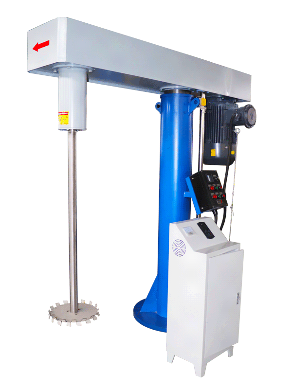
Hydraulic single axis disperser configuration for viscous mixing duties.
Formulation, Solids Loading, and Rheology
No disperser can compensate for a formulation that is fundamentally incompatible with the intended process. High solids loading, poor wetting, incompatible dispersants, and uncontrolled rheology can all produce defects that look like machine problems. When solids loading increases, the viscosity usually rises, the flow pattern changes, and the torque required to maintain circulation increases. At some point, the batch may become too stiff for a single-shaft machine to circulate effectively. The operating window should be defined with the actual formulation, not with a simplified model based on water or a low-viscosity test fluid.
Powder addition is especially important. Adding all the powder at once can create a thick layer of unwetted material, cause the blade to channel through a cavity, or generate large agglomerates that are difficult to break down later. Gradual addition under good surface movement usually gives better wetting. The feed point should be in the moving zone, not in a stagnant corner. The operator should watch for powder floating on the surface, dusting, or forming a mound that does not incorporate. If the batch thickens too quickly, a short pause or a change in blade position may be more useful than an immediate speed increase.
Powder Addition and Wetting Strategy
A controlled addition sequence can improve repeatability even when the machine and formulation remain unchanged. The vehicle or liquid components can be loaded first and brought into stable circulation. Powder can then be added at a rate that matches the machine's ability to wet and incorporate it. If the formulation allows, part of the liquid can be held back for later adjustment. This gives the operator room to correct viscosity without adding more solvent or dispersant after the fact. The exact sequence should be confirmed through trials because the best order depends on the powder surface, the liquid medium, and the dispersant chemistry.
- Confirm that the blade is immersed and circulating before powder addition begins.
- Add powder in a controlled stream or in portions where the flow can absorb it.
- Watch for floating powder, lumps, climbing, and sudden torque changes.
- Record the point at which viscosity develops and how the surface behavior changes.
- Use the hydraulic lift to correct blade depth only when the change supports the process.
- Avoid repeated speed increases that add heat without improving wetting.
Rheology modifiers and dispersants can change the process window significantly. A dispersant may reduce viscosity by improving particle separation, but overdosing can cause foaming, stability problems, or other defects. A thickener may improve suspension, but it can also suppress circulation and make deagglomeration harder. These effects should be evaluated with the disperser running, because a formulation that looks acceptable under low-shear mixing may behave differently under a high-shear blade. The machine and formulation should be developed together.
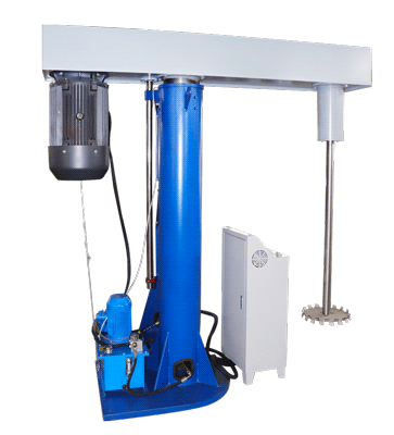
Single-shaft disperser arranged for viscous product processing.
Scale-Up and Process Verification
Scale-up is more than increasing the batch size. A larger vessel changes the flow pattern, the distance from the blade to the wall, the surface-to-volume ratio, and the heat removal capacity. A condition that produces good dispersion in a small vessel may produce poor circulation or excessive heat in a larger one. The usual approach is to maintain geometric similarity where possible, compare tip speed and power per unit volume, and then verify the result with measurements. No single scale-up rule fits every formulation, especially when the rheology is non-Newtonian.
Operators often try to scale by rpm. This is rarely reliable. If the vessel diameter and blade diameter increase, the same rpm produces a much higher tip speed and a different shear history. A better starting point is to preserve a relevant process parameter, such as tip speed, while checking whether the larger machine can still provide bulk circulation. If the larger batch becomes too viscous or the blade loads too heavily, the design may need a different blade, a different fill level, or a different addition procedure. These changes should be tested rather than assumed.
Measurements That Support Scale-Up
Useful process data includes batch temperature, torque or drive load, dispersion time, blade position, addition rate, and the qualitative appearance of the batch. Quality data may include fineness of grind, particle size distribution, rheology, density, color strength, gloss, stability, or presence of voids. The exact set depends on the product. The important point is to record both machine conditions and product results so that the relationship between them can be understood. Without this record, a successful batch cannot be reliably repeated or transferred to another machine.
A structured trial plan is more valuable than a single demonstration. Begin with a safe operating window, then vary one factor at a time: speed, blade position, powder addition rate, or dispersant level. Stop the trial if temperature rises too quickly, the vortex becomes unstable, or the product shows signs of over-mixing. Take samples at several points and evaluate them with methods that reflect the real quality requirement. For a coating, that may be fineness of grind and gloss. For a ceramic slip, it may be rheology and sedimentation. For an adhesive or sealant, it may be viscosity, uniformity, and absence of lumps.
Scale-up should also include a cleaning and changeover check. A larger machine may be harder to drain, clean, and inspect. Product that remains on the shaft, blade, or vessel wall can contaminate the next batch or reduce yield. The hydraulic lift can improve access, but the vessel and blade still need a practical cleaning path. If the product is sensitive to cross-contamination, the contact materials and surface finish should be reviewed with the supplier. These details are easier to address before installation than after the equipment is in place.
Selection, Installation, and Troubleshooting
Selecting a hydraulic single axis disperser should start with a clear process brief. The brief should describe the product, the intended batch size, the viscosity range, the solids loading, the target dispersion quality, the required temperature limit, and the available utilities. It should also identify the main difficulty: powder wetting, agglomerate breakdown, bulk circulation, air entrainment, heat, cleaning, or changeover. A machine selected only by batch volume may miss the factor that controls success. A machine selected around the dominant process problem is more likely to perform as expected.
What to Confirm Before Purchase
Ask for a configuration review based on the actual formulation. Confirm the blade style and diameter, the vessel dimensions, the shaft position range, the control functions, the contact materials, and the cleaning method. Check how the hydraulic lift behaves during loading, sampling, and maintenance. Review the safety features and the operating envelope. If trials are possible, run them with representative material rather than a simple model fluid. A trial with the real powder and liquid can reveal wetting problems, torque spikes, or foaming that would not appear in a water-based test.
- Describe the product rheology at the start, during, and end of the batch.
- Provide the intended batch size and the minimum and maximum working volume.
- State the powder addition method and the required wetting time.
- Define the quality target with a measurable test, not only a visual description.
- Confirm the available blade and vessel configuration with the supplier.
- Review contact materials for wear, corrosion, and contamination risk.
- Plan for cleaning, drainage, sampling, and operator access.
After installation, establish a baseline procedure before making changes. Record the blade position, speed, addition sequence, batch temperature, and mixing time for a successful batch. Use that baseline to troubleshoot. If dispersion quality drops, compare the current batch with the baseline instead of changing several variables at once. If torque rises, check whether the solids loading, addition rate, or viscosity has changed. If foam appears, check the shaft immersion, surface vortex, and speed. If lumps persist, check the powder feed point, wetting sequence, and dispersant level before assuming that the machine needs more power.
Maintenance should focus on the components that affect process consistency. Inspect the blade for wear, bending, or buildup. Check the shaft for runout and cleanliness. Review the hydraulic lift for smooth movement and correct positioning. Confirm that the controls repeat the intended speed and sequence. A small change in blade condition can alter flow and shear, especially in a high-viscosity batch. Keeping records of blade condition and process performance helps distinguish normal wear from a formulation problem.
The most reliable dispersion process is built around the product, not around a single machine setting. The hydraulic single axis disperser can be a practical choice for viscous mixing when the blade, vessel, lift position, speed, and feed strategy are matched to the formulation. It is equally important to recognize the limits. Extremely high yield stress, poor wetting chemistry, or excessive solids loading may require a different process strategy rather than a higher speed. A disciplined trial plan, clear measurements, and a repeatable operating procedure will provide more value than a headline performance claim.
Before finalizing an equipment choice, verify the working concept with representative material. Confirm the target quality, the acceptable cycle time, the temperature limit, and the cleaning requirement. Then review the offered configuration with TENCAN and document the approved operating window. This approach supports better decisions for laboratory development, pilot production, and full-scale manufacturing, and it keeps the focus on the dispersion result rather than on the machine alone. Additional details about the TENCAN hydraulic single axis disperser can be reviewed against the application requirements before a final selection is made.