

Product features
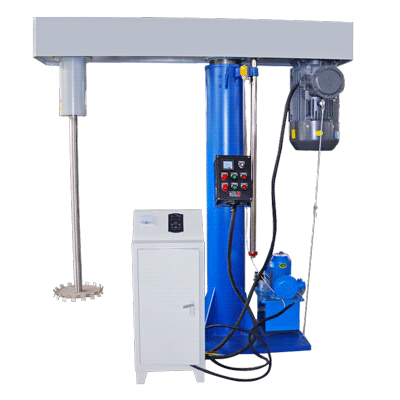
Hydraulic positioning
The lift provides a means of positioning the working head relative to the vessel and accessing the batch.
Variable-speed dispersion
The source describes frequency-controlled speed adjustment for matching disc action to the formulation and stage of preparation.
Single-shaft arrangement
The working shaft carries the dispersing assembly, allowing the disc and vessel relationship to be selected for the process.
Configurable installation
Vessel, lifting travel and electrical package should be specified with the formulation, access requirements and available site services.
Applications
Coating formulations
Evaluate pigment incorporation and dispersion in compatible coating systems, considering solids content, viscosity and the required finish.
Inks and colourants
Compare preparation conditions while checking residual agglomerates and the formulation's application-specific quality criteria.
Adhesive and chemical slurries
Assess mixing or dissolution in suitable liquids with drive load and the selected disc geometry taken into account.
Evaluating results
Dispersion quality
Measure remaining agglomerates or uniformity using a method relevant to the formulation rather than treating speed as proof.
Aeration and temperature
Observe air incorporation and heating as disc speed and immersion are varied during representative trials.
Batch consistency
Compare samples from different vessel locations and repeated batches using the same preparation and sampling procedure.
These are evaluation points for a sample trial, not measured results for a specific sample. Confirm performance under your actual operating conditions.
How it works
Position the assembly
Secure a compatible vessel and set the disc at the prescribed working position before starting the drive.
Apply rotating-disc action
Disc motion creates local shear, impact and friction, distributing material through the liquid and breaking suitable agglomerates.
Stop and inspect
Stop the machine before raising the assembly or accessing the batch, then use measured results to refine the procedure.
Construction and configuration
Hydraulic lift and guide
Check travel, load and vessel access as part of the selected machine's mechanical arrangement.
Drive and shaft
The motor and transmission must match the disc, formulation and expected working load for the chosen specification.
Controls and electrical package
Confirm the actual control and electrical configuration; suitability for hazardous environments requires a specifically verified equipment package.
Technical specifications
Compare the listed specifications and configurations. Scroll horizontally to view the complete table.
Specification table 1
| Model specifications | Host power (KW) | Maximum speed (r/min) | Dispersion disc diameter (mm) | Lifting stroke (mm) |
|---|---|---|---|---|
| FS-5.5 | 5.5 | 1400/2800 | 100-200 | 800 |
| FS-7.5 | 7.5 | 1400/2800 | 100-200 | 800 |
| FS-11 | 11 | 1400/2800 | 100-200 | 800 |
| FS-15 | 15 | 1400/2800 | 100-200 | 800 |
| FS-18.5 | 18.5 | 1400/2800 | 100-200 | 800 |
| FS-22 | 22 | 1400/2800 | 100-200 | 800 |
| FS-37 | 37 | 1400/2800 | 100-200 | 800 |
| FS-45 | 45 | 1400/2800 | 100-200 | 800 |
| FS-55 | 55 | 1400/2800 | 100-200 | 800 |
Confirm the selected model, power supply, contact materials and operating conditions before ordering. Performance depends on the material and process.