
Hydraulic Dual-Shaft Disperser: Mixing Guide
A dispersion batch that runs longer than expected often looks like a formulation problem. The pigment is not wetting out, the filler forms lumps, or the final grind gauge reading stays stubbornly high. Operators add more dispersant, extend the cycle, or raise the speed, but the batch still shows streaks, agglomerates, or an unstable viscosity. In many of these cases, the formulation is not the first place to look. The mixer may be unable to keep high-viscosity material moving through the high-shear zone.
As solids loading rises and the liquid phase becomes less available, a product moves from a low-viscosity fluid into a paste, gel, or thixotropic mass. A single-shaft mixer then has to perform two conflicting jobs: circulate the entire batch and create intense local shear. A hydraulic dual-shaft disperser addresses that conflict with separate mixing and dispersing shafts, but the concept only works when the machine, vessel, and process are matched to the material.
The Real Bottleneck in High-Viscosity Dispersion
At low viscosity, a high-speed disc can pull material from the batch and generate a visible vortex. At high viscosity, that same disc may only carve a local cavity. The bulk material outside the disc zone can remain nearly stationary, so powder added at the surface is not transported into the shear field. Yield stress and shear thinning make the problem worse: the material moves readily near the impeller and behaves like a solid elsewhere.
A single shaft is therefore a compromise. A large impeller provides bulk turnover but low local shear. A small high-speed disc provides strong shear but limited pumping. Increasing shaft speed to compensate often raises temperature, pulls air into the batch, and creates a narrow active zone rather than a uniform product. The result is a batch that may look mixed at the top while hiding agglomerates near the wall or bottom.
Energy alone does not solve a flow problem. A mixer can draw high power while most of the batch remains outside the active zone, because power is concentrated near the impeller. That is why two machines with similar installed power can produce different results. The useful questions are where the shear is applied, how often the material passes through it, and whether the bulk flow is strong enough to refresh the zone. A dual-shaft design is valuable when it improves those three conditions without creating excessive heat or air entrainment.
The symptoms usually appear before the final quality test. Powder may build up on the vessel wall, the shaft, or the surface of the batch. The mixer may sound stable while the product shows color streaks, gloss variation, coarse particles on a grind gauge, or a viscosity that drifts from batch to batch. In more severe cases, localized overheating can damage heat-sensitive ingredients or cause solvent loss.
It also helps to separate dispersion from grinding. A disperser wets powders, breaks down loose agglomerates, distributes particles, and helps stabilize the suspension. It does not necessarily reduce the primary particle size of hard crystals or pigments. If the target requires true comminution, a bead mill or another milling step may be needed after dispersion. Expecting a disperser to perform that work can lead to excessive cycle times and unrealistic specifications.
Adding time is not a reliable fix. Once an agglomerate is fully wetted and stabilized, additional mixing may do little to break it. If the batch has already gelled or formed a stable foam, more shear can make the problem worse. The practical question is whether the mixer can exchange material between the bulk and the high-shear zone quickly enough, at a controlled temperature, before the formulation begins to degrade.
How a Hydraulic Dual-Shaft Disperser Works
A hydraulic dual-shaft disperser uses two shafts in the same vessel. One shaft usually carries a low-speed impeller for bulk movement; the other carries a high-speed dispersing element for localized shear. The TENCAN hydraulic dual-shaft disperser belongs to this equipment class. The hydraulic system on this type of machine is commonly used for shaft lift and positioning, which helps with vessel access, cleaning, and different batch heights. The exact shaft geometry, speed ranges, and control package should be confirmed with the supplier for each application.
The low-speed shaft is the bulk-flow system. Depending on the material, it may use an anchor, gate, helix, or paddle shape. Its job is not to create the finest dispersion; it is to keep the entire batch in motion, push material toward the high-speed shaft, and prevent stagnant layers at the wall and bottom. In a high-solids product, that bulk movement is what makes the high-shear zone effective. Without it, the disperser works only on the material that happens to reach the disc.
The high-speed shaft provides the dispersive action. A saw-tooth disc or similar high-shear element creates high velocity gradients near its teeth and tip. The strongest shear is close to the impeller, not throughout the entire vessel. Tip speed, disc diameter, tooth geometry, and immersion depth all influence how much energy reaches the agglomerates. The high-speed shaft also pumps material radially and can generate a vortex at low viscosity. In a viscous batch, the flow pattern is different, and the bulk impeller becomes more important.
The hydraulic lift changes how the machine is used. Lowering the shafts to the correct depth places the high-speed element in the working zone without letting it run too close to the bottom. Raising the carriage provides access for vessel changes, inspection, and cleaning. It can also allow the operator to adjust immersion as the batch level changes. Safe operation depends on guarding, limit controls, and a procedure that prevents movement while the shafts are running or while personnel are near the vessel.
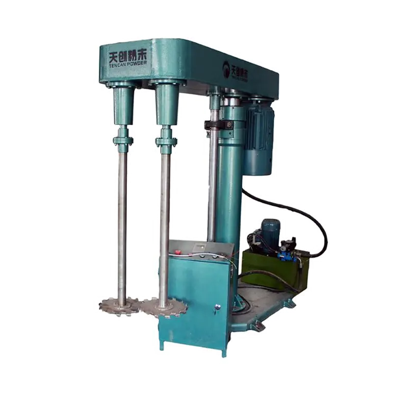
The hydraulic dual-shaft design separates bulk mixing from high-shear dispersion, so each function can be matched to the batch.
Configuration matters more than the label. Some machines use fixed shaft positions; others allow the high-speed shaft to be offset or the speeds to be controlled independently. Some are supplied with vacuum, jacketing, or vessel-scraping options. Each choice affects the flow pattern and the achievable dispersion. A dual-shaft machine with independent speed control can be tuned for a product with a changing viscosity during the batch, but the operator still needs a procedure that defines when each shaft should run and at what speed.
Power draw is a useful indicator, but it should be read together with viscosity and batch level. A rising power draw can mean the batch is becoming more viscous, the disperser is working in a heavier mass, or the shaft is too deep. A falling power draw can mean the product is thinning, the shaft has lost contact with the bulk, or the batch level has dropped. Operators should record power at defined points in the batch and compare trends rather than relying on a single limit value.
The equipment class also has limits. It is not a dry-powder mixer, and it is not a substitute for a bead mill when true particle-size reduction is required. It may be a poor fit for very low-viscosity products where a simple high-speed disperser already provides enough flow, or for highly abrasive systems where wear protection and contamination control need a different design. Those limits should be discussed before the machine is sized, not after the first batch.
Where the Two Shafts Do Different Work
In a well-designed dual-shaft system, three zones work together. The bulk zone near the low-speed impeller keeps the mass moving. The high-shear zone near the dispersing element breaks down agglomerates and creates fresh surface for wetting. The transition zone is where material exchanges between the two. If the transition is weak, the high-speed shaft may run at high power while only a small fraction of the batch receives shear. The visible result is a long cycle and inconsistent dispersion.
The order of addition is part of the mixing system. Powder should be added at a rate the bulk flow can absorb. If powder is dumped onto the surface faster than it can be wetted, it can form a skin, sink as dry pockets, or build up on the vessel wall. The low-speed shaft should be turning before the high-speed shaft is brought to dispersion speed, and the high-speed shaft should be positioned so that it draws wetted material rather than running in a dry or semi-dry pocket. These details often matter more than a small change in speed.
When independent speed control is available, the two shafts can follow different profiles during a batch. Early stages may need more bulk flow and moderate shear for incorporation. The dispersion stage may need higher shear once the powder is wetted and the batch is uniform. Letdown may need bulk mixing with limited shear to avoid air entrainment or temperature rise. A fixed-speed machine can still work, but the addition sequence and fill level must be chosen more carefully.
Shaft position relative to the vessel is also important. An off-center high-speed shaft can create a different flow pattern from a centered one. Too close to the wall, the disc may wear the wall or create a dead zone behind it. Too close to the bottom, it may damage the vessel or fail to draw material from above. The correct position depends on the impeller diameter, vessel diameter, fill height, and product rheology. It should be checked during commissioning and after any change in batch size.
The dual-shaft layout does not correct a poorly matched vessel. If the vessel is too wide for the low-speed impeller, wall layers may remain stationary. If the vessel bottom is dished or flat in the wrong way, the bottom layer may not exchange with the bulk. If the high-speed shaft is positioned where the bulk flow never reaches, it will disperse the same small volume repeatedly. Vessel drawings, impeller diameters, and working levels should be reviewed together before the machine is ordered.
Process Variables That Affect Dispersion Quality
Viscosity and solids loading
Viscosity is not a single number in a thixotropic product. It changes with shear rate, time, temperature, and the amount of powder that has been wetted. A formulation that is easy to mix at 50 percent solids can become a different material at 65 percent, even if the liquid phase is unchanged. The machine must be selected for the highest viscosity it will see during the batch, not only for the final letdown viscosity. High-solids batches also need enough free liquid to wet new powder; otherwise the mixer is asked to distribute a dry phase through a paste.
Flow, speed, and geometry
Tip speed is useful for comparing dispersers, but it is not a complete description of the process. Two discs with the same tip speed but different diameters create different shear histories and different pumping patterns. The number of passes through the high-shear zone also matters. A small disc at high speed can generate intense local shear, but if the bulk flow is poor, most of the batch may never enter that zone. The practical target is not maximum speed; it is enough shear, applied uniformly, without overheating or destabilizing the formulation.
Immersion depth controls how the disc interacts with the batch. If the disc runs too high, it may splash, entrain air, or fail to pump material from the lower part of the vessel. If it runs too low, it may not create the intended flow pattern and may damage the bottom. The correct depth changes with fill level and viscosity. During a batch, the operator should verify that the high-speed shaft is fully immersed and that the bulk impeller is moving material from the wall and bottom into the active zone.
Vessel geometry affects both shear and turnover. The clearance between the low-speed impeller and the wall influences wall exchange; the distance between the high-speed disc and the bottom influences bottom flow. A change in vessel shape can alter the result even when the formulation and shaft speeds are unchanged. When scaling between vessels, keep the important ratios in view, but verify them with a trial. Geometry changes that look minor on a drawing can create a new dead zone in a viscous product.
Addition, temperature, and air
Powder addition rate is one of the most common causes of dispersion problems. Fast addition can overwhelm the available liquid, create lumps with dry cores, and increase the demand on the disperser. Slow addition costs time but produces a more uniform wet-out. The right rate depends on the powder's bulk density, surface treatment, and tendency to agglomerate. In some products, adding powder under vacuum or with a controlled feeder improves consistency. In others, pre-dispersing the powder in a carrier liquid is more effective.
Temperature must be watched because mechanical energy becomes heat. High-shear dispersion can raise the batch temperature quickly, especially in a viscous product with poor heat transfer. That may be acceptable for a robust formulation, but it can damage temperature-sensitive polymers, surfactants, or pigments. Jacketing, controlled shaft speeds, and staged addition can help. The temperature sensor should measure the product, not only the jacket, and the batch record should show the maximum temperature reached during dispersion.
Air is another hidden variable. A vortex can entrain air at low viscosity, while a high-solids paste can trap air during powder addition. Foam or entrained bubbles may look like poor dispersion on a grind gauge and can affect density, conductivity, or coating appearance. Vacuum operation, slower addition, and appropriate shaft immersion can reduce air entrapment. The right solution depends on whether the air enters at the surface, with the powder, or through a leaking seal.
Batch size and fill level affect the flow pattern as much as the formulation. A vessel that is too full may limit surface movement and increase spill risk. A vessel that is too empty may place the high-speed shaft in a poor pumping position or leave the bulk impeller partially uncovered. Scale-down trials should use the same geometry and fill ratio as the intended production vessel whenever possible. If the geometry cannot be matched, the speed and addition procedure should be re-established rather than copied directly.
Selecting the Right Configuration for the Material
Selection starts with a written duty, not a single viscosity value. Define the batch size, the working volume, the highest and lowest viscosity during the process, the solids loading, the powder addition rate, and the target dispersion. State whether the product is Newtonian, shear thinning, thixotropic, or prone to yield stress. Include the maximum temperature, the required vacuum or pressure, the cleaning method, and the materials of construction. These inputs determine whether a dual-shaft design is appropriate and how the shafts should be arranged.
Wetted parts and seals deserve early attention. The product may be corrosive, abrasive, or sensitive to metal contamination. Elastomers must be compatible with the liquid phase and the cleaning agents. Shaft seals must handle the product viscosity, vacuum, and solvent exposure. A hydraulic system adds another maintenance boundary: hoses, fittings, and oil must be kept away from the product, and the lift system must be serviceable without compromising the mixing area. The supplier should confirm the actual materials and options for the intended application.
The hydraulic lift should be matched to the vessel and the workflow. The stroke must be enough to raise the shafts clear of the batch for cleaning and vessel changes. The carriage should be stable at the working height and should not drift during operation. Controls should prevent shaft rotation unless the carriage is in a safe position, and the system should include guards and clear lockout points. These are practical details, but they affect downtime, operator safety, and the risk of product contamination.
Shaft arrangement, lift access, and vessel geometry should be reviewed together during selection.
A dual-shaft disperser is not automatically the right choice for every high-viscosity product. A single high-speed disperser may be sufficient for a low-viscosity letdown or a product that wets easily. A planetary mixer may be better for a very stiff paste that cannot be pumped by an impeller. A bead mill may be required when the target is a narrow particle-size distribution below what dispersion alone can achieve. The decision should follow the mixing task: bulk flow, wetting, deagglomeration, heat transfer, and cleaning. The TENCAN hydraulic dual-shaft disperser should be evaluated against those tasks, not against a single speed or power figure.
A meaningful trial should reproduce the production addition sequence, not just the final formulation. Record the shaft speeds, tip speeds if available, addition time, batch temperature, vacuum level, and visual observations. Test the product at several points, not only at the end. A grind gauge, rheology, color, gloss, or filtration test can show whether the dispersion is uniform. If the trial requires a longer cycle than expected, check the flow pattern before increasing speed; more speed can hide a bulk-flow problem while adding heat and air.
Controls should make the process repeatable, not merely possible. Useful records include shaft speeds, power draw, batch temperature, vacuum level, addition time, and the point at which each stage begins. Recipe control can prevent operators from skipping a low-speed stage or raising the disperser speed before the powder is wetted. If the machine is used for multiple products, access control and cleaning status should be clear. The control package should fit the real workflow; a complex recipe system cannot compensate for a poorly matched vessel or an inconsistent powder feed.
Scale-Up, Cleaning, and Maintenance Checks
Scale-up cannot rely on keeping the same rpm. A larger disc has a higher tip speed at the same shaft speed, and a larger vessel has a different circulation time and heat-transfer area. Depending on the controlling mechanism, scale-up may use constant tip speed, constant power per unit volume, or a combination of criteria. The choice should be tested against the product, because a change that preserves shear may not preserve bulk flow. Pilot batches should be evaluated for dispersion quality, temperature rise, and cycle time at the same time.
Cleaning is easier when the machine is designed for access. The hydraulic lift should raise the shafts to a position where the impellers, shaft, and vessel can be inspected and cleaned. Dead zones around seals, shaft collars, and the vessel bottom should be accessible. If the product is changed frequently, cleanability and cross-contamination risk may be as important as dispersion performance. Cleaning validation should include the hydraulic area, not only the product-contact parts, because oil leaks or trapped material can create a separate risk.
Maintenance checks should focus on the parts that affect flow and product quality. Inspect the impellers for wear, distortion, or loose fasteners. Check shaft runout and coupling alignment. Look for seal leakage, hydraulic oil leaks, and damaged hoses. Confirm that the lift holds position and that limit switches work. A change in power draw, vibration, or batch time can be an early sign of wear or a change in the product. These records are more useful than a one-time inspection because they show trends.
Troubleshooting should start with flow, not speed. If the product is coarse, check whether powder is entering the high-shear zone and whether the batch is uniform before the final grind check. If the batch is overheating, review addition rate and shaft immersion before reducing dispersion time. If air is entrained, check the surface movement and the powder feeding method. These checks separate a formulation problem from a machine or procedure problem and prevent unnecessary changes to the recipe.
Safety checks should cover both the product and the hydraulic system. Shaft guards, emergency stops, and limit switches must be functional. The lift should be locked out before any work near the shafts, and the vessel should be secured against movement. Hydraulic hoses should be routed away from hot surfaces and operator access areas. Training should include what to do if the shafts stall, the lift drifts, or a seal leaks. These procedures protect people and also prevent small faults from becoming batch losses.
Before specifying a hydraulic dual-shaft disperser, confirm the process with the supplier using the actual material, the intended addition sequence, and the cleaning method. The machine should be selected for the difficult part of the batch, not the easy final letdown. A well-matched system gives the operator control over bulk flow and shear without turning every batch into a test.