
Horizontal Tube Furnace: Heating Zone Control
An inconsistent sintering result is rarely caused by the recipe alone. In many laboratories, two crucibles placed at the same nominal setpoint — one in the middle of the tube and one closer to the end — come out with different density, color, or phase composition. The controller displays a stable temperature, the program runs to completion, and yet the samples did not experience the same process. Understanding why that happens is the fastest route to a repeatable thermal cycle.
The gap between the number on the controller and the condition of the sample is where most tube furnace problems begin. A tube furnace is a deceptively simple machine — a refractory tube, a winding or array of heating elements, insulation, a thermocouple, and a controller — but the interaction between tube geometry, gas flow, and load position determines whether the process repeats from run to run. This article examines those interactions in practical terms: how heat is distributed inside the tube, how atmosphere and tube material narrow or widen the usable process window, how loading practice changes results, and which configuration details deserve attention before a furnace is purchased or accepted into routine use.
Why the Hot Zone, Not the Setpoint, Determines Sample Quality
Every tube furnace has a physical hot zone — the length of tube over which the temperature stays within a defined band of the setpoint. Suppliers usually describe this as an isothermal zone or uniform temperature zone, and it is normally shorter than the tube itself. Near the ends of the tube, heat is lost through the end caps, flanges, and gas connections, so temperature falls off. If a sample boat sits in that transition region, the sample sees a lower temperature than the controller reports, and the deviation grows as the setpoint increases.
This is why two identical samples can produce different results in the same run. The control thermocouple is fixed in one position, usually at the center of the heated length or inside a protective well, and it regulates the furnace based on that single point. Any material placed elsewhere along the tube is exposed to a different temperature profile. When the process is sensitive — solid-state reaction, binder burnout, or densification near a phase boundary — a difference of a few tens of degrees is enough to change the outcome.
The practical response is not to distrust the controller but to characterize the tube. A profile test with an independent thermocouple moved in steps along the tube axis shows where the uniform region begins and ends at each working temperature. Once that map exists, sample placement becomes a decision rather than a guess, and the effective working length of the furnace is known for each process. Repeating the test after changing tube material, adding end plugs, or altering gas flow is worthwhile, because all three change the profile.
Furnaces configured with multiple independently controlled heating zones address this issue directly. By trimming the power delivered to the end zones, the operator can extend the uniform region and compensate for end losses. Multi-zone control adds cost and requires more attention during setup, but for processes where the entire load must see the same temperature — multi-sample sintering, diffusion couples, or substrate annealing — it often removes the need to restrict samples to a narrow central band.
How a Horizontal Tube Furnace Is Built and How Heat Moves Through It
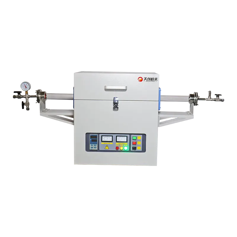
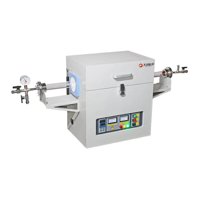
A horizontal tube furnace consists of a cylindrical or split-cylindrical heating chamber through which a process tube passes. Heating elements surround the tube and radiate heat inward. Between the elements and the outer shell sits insulating material — ceramic fiber blanket, brick, or a combination — that reduces heat loss and protects the housing. The tube itself is supported at both ends and passes through the chamber, so the process atmosphere inside the tube stays separated from the elements outside it.
Heat reaches the sample in three ways. Radiation from the tube wall dominates at high temperature, conduction matters where the sample boat touches the tube, and convection becomes significant when gas flows through the tube. Because the balance among these mechanisms shifts with temperature, an empty tube and a loaded tube do not heat identically. A dense boat sitting in the middle of the tube absorbs energy and creates a local cold spot unless the controller has enough power reserve and the profile allows adequate soak time.
The Working Tube: Material, Diameter, and Length
The tube is the component that most directly defines what the furnace can do. Its diameter sets the maximum sample size and the gas velocity for a given flow rate; its length determines how much of the tube extends outside the heated chamber for cooling and connections; its material determines the maximum service temperature and chemical compatibility. A larger diameter tube increases the cross-sectional area, which lowers gas velocity and lengthens purge times, but allows larger boats and more samples per run.
Tube wall thickness affects both thermal response and mechanical strength. Thicker walls heat and cool more slowly, which lengthens cycle times but also smooths temperature fluctuations. Thin walls respond faster but are more vulnerable to thermal shock, particularly during rapid cooling or when a cold gas is introduced into a hot tube. For processes with aggressive heating and cooling ramps, wall thickness and end support design deserve as much attention as the maximum temperature rating.
Heating Elements, Insulation, and Zone Layout
Element type and placement define the achievable heating rate and the shape of the temperature profile. Elements distributed uniformly along the chamber produce a broad, relatively flat profile; elements concentrated in the center produce a hotter core with steeper fall-off toward the ends. Insulation thickness and the quality of the end sealing determine how much heat escapes at the tube ends and therefore how abruptly the profile drops.
Split-chamber designs allow the furnace to be opened for faster cooling or for inserting a large workpiece, but they lose more heat at the seam and generally require more power to hold a given setpoint. Non-split designs hold temperature more consistently and are the usual choice for processes that demand tight uniformity. The choice is a trade-off between accessibility and thermal stability, and it should follow the process requirement rather than convenience.
Where the Thermocouple Sits Matters More Than Its Accuracy
A calibrated thermocouple measuring the wrong location produces a confident, precise, and incorrect answer. In most furnaces, the control thermocouple measures the heating chamber or a well adjacent to the tube, not the sample. The difference between that reading and the actual sample temperature depends on tube material, wall thickness, gas flow, and load. Quartz transmits radiation differently than alumina, and a flowing gas stream carries heat away from the sample in a way that a static atmosphere does not.
For processes with tight tolerance, an independent measurement — a second thermocouple positioned near the sample, or a sacrificial test run with a thermocouple inserted through the gas outlet — gives a much better basis for setting a controller offset. Once the relationship between the controller reading and the sample temperature is known at the working setpoints, it can be applied consistently. It should be rechecked whenever the tube, the load, or the gas flow changes.
Atmosphere Control: Purging, Flow Rate, and Vacuum Operation
Atmosphere is the second half of the process. A horizontal tube furnace with end flanges and gas connections can run under inert gas, reducing gas mixtures, oxidizing atmospheres, or vacuum, but each mode has its own practical constraints. The purpose of the gas system is not simply to supply a gas but to displace the original atmosphere and then maintain the required composition for the duration of the thermal cycle.
Purging is a volumetric problem. The time needed to displace air from the tube depends on tube volume, flow rate, and how effectively the gas sweeps dead spaces around boats and supports. A short, narrow tube purges quickly; a long, large-diameter tube with a bulky load can require a substantially longer purge. Purging at a high rate shortens the time but increases gas consumption and can disturb fine powders or cool the load unevenly. Many laboratories prefer a moderate purge followed by a lower maintenance flow during the soak.
Flow direction also matters. Gas entering at the end where samples are loaded pushes residual atmosphere and evolved volatiles toward the outlet, which is generally the preferred arrangement for processes that release decomposition products. Gas flowing counter to the sample can be useful when the load must be protected from contaminants carried from upstream, but it can also trap volatiles around the sample. Whichever direction is chosen, the outlet should be positioned so that exhaust gases leave the working area safely.
Vacuum operation introduces a different set of considerations. Under reduced pressure, convection is largely eliminated, so heat transfer relies more on radiation and conduction, and the temperature profile can shift. Sealing becomes critical: flange seals, O-rings, and feedthroughs must be compatible with both the temperature at their location and the process chemistry. Vacuum also changes the behavior of volatile species in the sample, which can be an advantage for degassing and a problem for materials that evaporate at process temperature.
Oxygen ingress is the most common atmosphere fault. It usually comes from three places: incomplete initial purge, leaks at flange seals or gas fittings, and back-diffusion at the outlet when flow stops while the tube is still hot. A simple improvement is to maintain a small positive flow during cooling rather than shutting the gas off immediately, and to leak-check the assembly periodically at operating temperature, when seals expand and joints move.
Choosing Tube Material for the Temperature and Chemistry You Need
Tube material is a chemical and thermal decision, not only a temperature rating. Quartz offers good thermal shock resistance and transparency, which is useful when the process needs to be observed, but it softens at high temperature and reacts with certain alkaline and strongly reducing environments. Alumina and mullite hold their shape at higher temperatures and resist many corrosive atmospheres, but they are more sensitive to rapid temperature change and are opaque. Metal tubes, including stainless steel and high-nickel alloys, are tough and easy to seal, but they can interact with the sample and have their own temperature limits.
The correct question is not which material has the highest rating but which material survives the entire cycle in the specific chemistry. A tube that performs well in inert gas may fail quickly in a reducing atmosphere at the same temperature. A tube that resists a corrosive vapor at the working temperature may still be attacked during cool-down, when condensates form on cooler surfaces. Reviewing the process gas, any volatile species released by the sample, and the cooling atmosphere together gives a more reliable answer than any single specification line.
| Tube material class | Typical strengths | Points to check before use |
|---|---|---|
| Fused quartz | Good thermal shock resistance, transparent for visual monitoring, low contamination in many oxide processes | Practical temperature ceiling and softening behavior; compatibility with alkaline and strongly reducing atmospheres; support at both ends |
| Alumina / mullite | Higher usable temperature, good chemical inertness in many atmospheres, dimensionally stable | Sensitivity to rapid heating and cooling; thermal expansion at flanges; opacity prevents visual inspection |
| High-nickel alloy | Tough, easy to seal and connect, tolerant of mechanical handling | Reaction with the sample or process gas; lower usable temperature than ceramic tubes; expansion at seals |
| Stainless steel | Readily available, straightforward sealing, suitable for lower-temperature work | Oxidation and scaling at high temperature; potential contamination of sensitive samples |
Whatever the material, the tube should be supported so that it is free to expand along its axis. Rigid clamping at both ends can introduce stress that leads to cracking during heating, and the failure often appears as a crack near a flange rather than in the heated zone. End supports that allow axial movement while holding the tube centered prevent a large share of mechanical tube failures.
Sample Loading and Thermal Profile Design
The load is part of the thermal system. A heavy boat, a deep powder bed, or a stack of substrates changes how heat enters the sample and how volatiles escape. In a deep powder bed, the surface reaches temperature well before the interior, and decomposition products must diffuse out through the bed. The result can be a gradient in both temperature and chemistry that is invisible from the controller display.
Boats, Crucibles, and Contact with the Tube
Boat material should be chosen for chemical compatibility first and thermal mass second. Alumina boats are common for oxide work, quartz for processes where transparency or high purity matters, and metal boats where mechanical strength is needed at moderate temperature. The boat should be small enough to leave clearance inside the tube, because a boat that contacts the tube wall creates a conduction path and a local cold spot, and it can also scratch or stress the tube during insertion.
Placing the boat on a thin support, or suspending it so that it sees radiation from all sides, often improves uniformity compared with letting it sit directly on the tube wall. The trade-off is mechanical complexity and the risk of the support itself contaminating the sample. Where the process tolerates direct contact, a shallow bed spread over a wider area usually performs better than a tall, narrow pile of the same mass.
Ramp Rate, Soak Time, and Controlled Cooling
Ramp rate is limited by two separate constraints: what the furnace can deliver and what the sample can survive. The furnace limit depends on available power, insulation, and the thermal mass of the tube and load. The sample limit depends on thermal shock resistance, on reaction kinetics, and on whether volatile release must be staged slowly to avoid cracking, foaming, or spalling.
Soak time should be justified by the process rather than by habit. For solid-state reactions, the soak must be long enough for diffusion; for binder removal, long enough for the organics to leave; for annealing, long enough for the microstructure to stabilize. Extending the soak beyond what the process requires costs energy and element life without improving the result. A short trial matrix — two or three soak times at the same temperature with the same load configuration — quickly identifies where additional time stops making a difference.
Cooling deserves the same attention as heating. In many processes the final properties are set during cooling, and an uncontrolled cool-down in the wrong atmosphere can oxidize a surface or allow an unwanted phase to form. Programming a controlled cooling segment, with gas flow maintained until the load is below the temperature at which it reacts with air, protects the work that the heating cycle accomplished.
Single-Zone and Multi-Zone Configurations: Which One Fits the Process
A single-zone furnace is simpler, less expensive, and easier to maintain. It suits small samples placed consistently in the center of the tube, short tubes where end losses are limited, and processes that tolerate a modest temperature gradient. For many teaching, screening, and preliminary research tasks, a single-zone configuration delivers all the control that is actually needed.
Multi-zone furnaces become worthwhile when the sample length is substantial relative to the tube, when several samples must be treated identically, or when the process has a narrow tolerance around a phase transition or a densification window. In these cases, end-zone trimming can flatten the profile and increase the usable working length considerably. The cost is not only financial: each additional zone adds a controller channel, another thermocouple to verify, and another variable to document during method development.
A middle path is to keep a single-zone furnace but control the ends physically — with insulating end plugs, radiation shields, or a shorter tube with well-sealed flanges. These measures reduce end losses and can extend the uniform region without adding control channels. They also change purge behavior, so any modification of this kind should be followed by another profile check at the working temperature.
Diagnosing Common Problems in Tube Furnace Processing
Most faults fall into a small number of categories, and each has a characteristic signature. Recording the symptom, the position of the sample in the tube, the gas flow, and the actual thermal profile makes diagnosis much faster than changing one variable at a time without notes.
| Symptom | Likely cause | What to check |
|---|---|---|
| Samples at one end differ from samples at the other | Uneven temperature profile or asymmetric gas flow | Map the profile with a traveling thermocouple; check for a restricted or partially blocked outlet |
| Surface discoloration or oxidation | Oxygen ingress or insufficient purge | Leak-check flanges and fittings; extend purge time; maintain flow during cool-down |
| Incomplete reaction at the correct setpoint | Sample temperature lower than the controller reading | Cross-check with an independent thermocouple near the load and apply a measured offset |
| Cracking, bloating, or foaming of the sample | Ramp too fast or volatile release too rapid | Reduce the ramp rate and add intermediate hold steps |
| Tube breakage near a flange | Rigid mounting or thermal expansion stress | Allow axial movement; verify support alignment and clearances |
| Erratic or drifting temperature control | Thermocouple fault, loose connection, or element aging | Verify thermocouple response, terminal tightness, and element resistance |
Two of these deserve more comment. The first is the discoloration problem, which is often blamed on the gas supply when the real cause is a leak path or a cool-down that allows air to enter. Checking with a small positive pressure rather than a vacuum, and watching the outlet during the transition from hot to cold, usually reveals the source. The second is the incomplete-reaction problem, which is frequently a placement issue rather than a furnace capability issue. Moving the same load into the verified uniform region often resolves it without any change to the program.
Erratic control has a different character. If the deviation appears suddenly after many successful runs, the cause is usually hardware: a thermocouple that has drifted, a terminal that has loosened under thermal cycling, or an element that has aged and changed resistance. If it appears after a change in configuration — a new tube, a new gas flow rate, or a new load — the cause is more likely thermal, and the profile should be re-measured before the controller is adjusted.
Specification Checklist When Selecting a Horizontal Tube Furnace
Selection should start from the process, not from the product list. The following points cover the decisions that most often determine whether a furnace performs as expected in routine laboratory work.
- Maximum working temperature with margin. The continuous working temperature, not the short-term peak, should exceed the highest process setpoint by a comfortable margin so that elements and insulation are not run at their limit.
- Tube diameter and length. Diameter must accommodate the boat or substrate plus clearance; length must allow for the heated chamber, end cooling, and gas connections.
- Uniform zone length at the working temperature. This is the number that determines how many samples can be processed together, and it should be confirmed under the intended gas flow.
- Single-zone or multi-zone control. Choose based on how much of the tube must be isothermal, not on the maximum available configuration.
- Tube material options. Confirm which materials are available for the intended atmosphere and temperature, and how the tube is supported.
- Flange and sealing arrangement. Consider gas-tight sealing, vacuum capability, thermocouple and gas feedthroughs, and how seals behave at operating temperature.
- Gas inlet and outlet design. Direction of flow, outlet size, and whether the exhaust can be routed safely away from the working area.
- Controller capability. Number of program segments, ramp and dwell control, over-temperature protection, and whether offset or multi-zone trimming is possible.
- Maintenance access. Element replacement, thermocouple replacement, and tube exchange should be possible without dismantling the entire assembly.
Among these, the uniform zone length is the specification most often overestimated at the purchasing stage and most often disappointing during use, because it is quoted under ideal conditions. A furnace that holds a narrow band at a moderate flow may show a shorter band when a large load is inserted or when the flow is increased to shorten purging. Asking how the uniform zone was determined — empty or loaded, static or flowing — clarifies what the number actually means.
Matching Configuration to Typical Laboratory Applications
Different thermal processes stress different parts of the furnace. Powder calcination and solid-state synthesis emphasize temperature uniformity and atmosphere stability, because the reaction depends on the whole bed reaching the same condition. Thin-film annealing and diffusion work emphasize profile flatness and clean atmosphere, since surface chemistry is the controlling factor. Binder removal and organic burnout emphasize controlled volatile release, which places more demand on the program than on the hardware.
Atmosphere-reactive processes — reduction, carburization, or work with oxygen-sensitive materials — place the highest demand on sealing and purge design. Here the furnace should be selected with the gas path in mind: the number of sealed penetrations, the ability to maintain positive pressure, and the behavior of the outlet during cooling. A furnace that performs well for air sintering may be a poor choice for a reducing process unless the flange and seal arrangement supports it.
Corrosive or high-purity processes add a materials question. When contamination is a concern, the tube, boats, and supports become the critical components, and the choice of tube material often matters more than the furnace's headline temperature rating. In these cases, the most useful specification is not the maximum temperature but the combination of tube material, atmosphere, and temperature that the manufacturer supports as a working configuration.
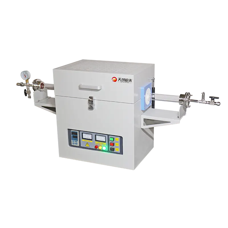
Laboratory horizontal tube furnace designs from TENCAN (Changsha Tianchuang Powder Technology Co., Ltd) are offered with configurable tube and control options so that the working configuration can be matched to the intended atmosphere and temperature range rather than to a single fixed specification.
Commissioning Checks Before the Furnace Enters Routine Use
Commissioning is a short investment that prevents months of unexplained variation. The sequence below is straightforward and can be completed before any valuable samples are committed to the furnace.
- Empty-tube profile test. Record the temperature at several points along the tube axis at the intended setpoints, both with static atmosphere and with the working gas flow.
- Leak and purge verification. Confirm that the assembly holds a small positive pressure and that purge times are long enough to displace the original atmosphere from the tube and around the load.
- Thermocouple cross-check. Compare the controller reading with an independent measurement at the sample position and document the offset at each working setpoint.
- Trial run with a dummy load. Use a representative boat and charge to verify that the thermal profile and gas behavior are unchanged by the load.
- Documentation. Record the verified configuration — tube material, load position, gas type and flow, program steps — so that future runs start from a known baseline.
The output of commissioning is not a certificate but a working reference. When a result later deviates, the documented baseline allows the operator to distinguish a process change from an equipment change, which is usually the hardest distinction to make during troubleshooting. It also makes method transfer between furnaces far more reliable, because the receiving laboratory can reproduce the same verified conditions instead of copying a program and hoping for the same outcome.
It is worth repeating the profile test whenever the configuration changes materially. A new tube, a different boat material, an increased gas flow, or a heavier load all shift the relationship between the controller and the sample. Re-measuring takes an afternoon; chasing an unexplained deviation can take weeks.
Practical Next Steps
Start with the process, not the furnace. Define the required temperature, atmosphere, load geometry, and the tolerance that the application actually allows, then decide how much of the tube must hold that condition. That single decision determines whether a single-zone or multi-zone configuration is appropriate, how the tube should be supported, and where samples can reliably be placed.
From there, treat atmosphere and thermal profile as one system. Purge time, flow rate, ramp rate, and cooling conditions interact, and changing one without re-verifying the others is the most common source of run-to-run variation in laboratory tube furnace work. A verified baseline profile, documented once and reused, is usually more valuable than any single equipment upgrade.
Finally, be conservative about specifications. Where a value is not confirmed for a specific configuration, testing under the intended conditions is the only reliable basis for a decision. Furnace suppliers can support that testing by clarifying how a rating applies to a particular tube material, atmosphere, and load, but the final verification belongs in the laboratory where the process will run.