
Shear Emulsifier: Stability and Scale-Up
Why Emulsion Stability Starts at the Rotor–Stator Gap
A clean, uniform emulsion immediately after mixing can still develop creaming, coalescence, or a watery layer within days. Formulators often respond by adding surfactant or raising the speed setting. Those changes may help, but they can also hide the real problem: the product never received enough controlled shear in the working zone, or it received useful shear together with excessive heat and air. In a shear emulsifier, most of the energy is intended to be concentrated in the narrow gap between a rotating rotor and a stationary stator. The geometry of that gap, the flow path through it, and the way the batch is recirculated past the head usually matter more than a single rpm number.
An emulsion is not stabilized simply because the droplets are small. Stability depends on droplet size distribution, interfacial film strength, viscosity of the continuous phase, density difference between phases, and the absence of coalescence triggers. A shear emulsifier influences the first, third, and fifth factors directly. It breaks large droplets into smaller ones and distributes them through the continuous phase. It also changes the effective viscosity of the system as the internal phase is subdivided. If the emulsifier creates a narrow, reproducible droplet size distribution, the surfactant has a better chance to cover the new interface before droplets collide and merge again.
This is why two batches made with the same formula can behave differently when the mixing sequence changes. A short, intense pass through a rotor–stator head may produce fine droplets, but if the product is then held under low shear for a long time, Ostwald ripening and creaming can still occur. Conversely, a longer low-intensity mix may incorporate more air and heat without improving the droplet size. The practical task is to find the energy input, residence time, and temperature window that produce the required distribution without damaging the ingredients.
The first diagnostic question is therefore not “what is the maximum speed?” but “where is the shear being applied, and for how long?” In a batch shear emulsifier, the product may pass through the head many times. In a recirculating arrangement, the number of passes depends on batch volume, flow rate, and run time. In a small laboratory vessel, the head may be partially immersed, which changes both pumping and aeration. These are process variables, not merely machine settings. They should be recorded alongside the formula so that a stable laboratory batch can be repeated and transferred to a larger system with a rational basis.
For anyone comparing a laboratory shear emulsifier with a simple stirrer, the difference is the concentrated shear zone. A paddle or anchor agitator moves the bulk and creates a vortex, but it does not necessarily generate the local velocity gradient needed to deform and break droplets. A rotor–stator head forces the product through a restricted region where the velocity changes sharply over a short distance. That is the region that does the emulsification work. The rest of the vessel is mainly responsible for bulk turnover, heat transfer, and keeping the composition uniform.
Inside a Shear Emulsifier: Rotor, Stator, and Flow Path
The TENCAN shear emulsifier is a laboratory rotor–stator mixing unit for emulsification and dispersion. Its exact head design, vessel, motor, and wetted materials are configuration details that should be confirmed on the product page and in the quotation, because a shear emulsifier is a system rather than a motor and shaft alone. The following discussion explains the decisions that matter when evaluating that system.
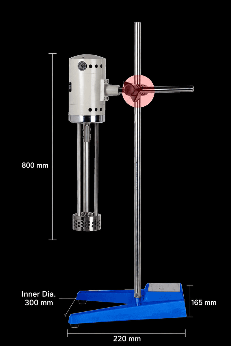
A rotor–stator head has two main functions. First, it acts as a pump, drawing product into the center of the head and pushing it outward through slots, holes, or a defined annular gap. Second, it creates high shear in the region where the rotating and stationary surfaces are closest. The balance between pumping and shear depends on the rotor diameter, the number and shape of the teeth or slots, the clearance, and the speed. A head designed for high pumping may move a viscous batch effectively but produce a wider droplet size distribution. A head designed for intense local shear may create finer droplets but handle less bulk flow, especially as viscosity rises.
Rotor Tip Speed and Shear Rate
Rotor tip speed is proportional to rotor diameter multiplied by rotational speed. This is a useful scale-up parameter because it describes the linear velocity at the outer edge of the rotor. In an idealized gap, the shear rate can be estimated as tip speed divided by gap width. The word idealized matters here. Real flow through a toothed head is three-dimensional, turbulent in places, and strongly affected by viscosity and viscoelasticity. The calculation is still useful for comparing two geometrically similar heads, but it should not be treated as a guarantee of droplet size.
When a formulator increases speed, several things happen at once. The local shear stress rises, which can break droplets more effectively. The pumping rate also rises, so the batch passes through the head more often. More mechanical energy is converted to heat, and more air may be entrained at the surface. If the surfactant system is sensitive to temperature or if the dispersed phase contains volatile components, the benefit of higher speed may be offset by thermal damage or composition shift. A design of experiments that changes speed, time, and temperature independently is usually more informative than a single speed ramp.
Stator Geometry and Residence Time
The stator controls how long the product remains in the high-shear zone and how it exits the head. A tight clearance and a long flow path increase residence time and energy density, but they also increase the risk of overheating and make cleaning more difficult. Open slots and larger openings improve flow and cleanability but may reduce the maximum shear stress for a given speed. The right choice depends on the target droplet size, the viscosity of the continuous phase, and whether the product contains solids that could bridge the gap.
Residence time in the head is short, often a fraction of a second per pass. The total energy input is therefore a product of shear intensity and the number of passes. This is why two runs at the same speed can produce different results if one is recirculated for longer or if the vessel geometry changes the turnover rate. In a small batch, the head may process the entire volume many times per minute. In a larger vessel, the same head may process only a fraction of the volume in the same period. The number of effective passes should be estimated or measured, not assumed from run time alone.
Sealing, Headspace, and Temperature Control
Shaft sealing and headspace are often overlooked during selection. A seal that is compatible with the formulation must prevent leakage and avoid contamination from lubricants or wear particles. For products containing solvents, the seal and wetted materials need to be checked against the chemical exposure. For products that are sensitive to oxidation, the ability to blanket the vessel with inert gas or operate with limited headspace may be more important than a small increase in shear.
Temperature control is part of the emulsification system. Mechanical energy raises product temperature, and the rate of temperature rise depends on batch mass, motor power, run time, and heat removal. A jacketed vessel or an external cooling loop can help, but the sensor location matters. A probe near the vessel wall may not represent the temperature inside the shear zone. If the formulation contains heat-sensitive proteins, fragrance components, or low-boiling solvents, short runs with controlled cooling and adequate rest periods may be preferable to a single long run.
Matching the Shear Emulsifier to the Formulation
No single rotor–stator configuration is ideal for every emulsion. The formulation determines whether the limiting factor is droplet breakup, bulk mixing, heat removal, or contamination control. A useful approach is to identify the dominant formulation signal before comparing equipment. The following table shows how common signals translate into selection questions. It is a qualitative guide, not a substitute for testing with the actual formula.
| Formulation signal | What it usually means | What to verify in a shear emulsifier |
|---|---|---|
| Low viscosity, low dispersed-phase fraction | Droplet collision is less hindered, but the batch can aerate easily | Head immersion, vortex control, tip speed range, and the ability to run without excessive air entrainment |
| High viscosity or semisolid consistency | Bulk turnover and pumping may limit performance more than local shear | Motor torque at low speed, head design for viscous flow, vessel fit, and whether a separate bulk agitator is needed |
| Heat-sensitive ingredients | Energy input can raise temperature quickly in a small batch | Temperature monitoring, cooling options, short-run capability, and minimum working volume |
| Solvent or volatile phase | Seal compatibility and vapor containment become critical | Wetted materials, seal type, headspace, and ventilation or inerting provisions |
| Abrasive or hard particles | Clearance and wear parts may control service life | Gap size, rotor and stator materials, seal protection, and cleanability |
| Foam-prone system | Air bubbles can mimic droplets and destabilize the film | Head position, speed range, vessel geometry, and the ability to degas under controlled conditions |
Low-Viscosity Emulsions
Low-viscosity oil-in-water systems are often the easiest place to start, but they are also prone to aeration. A head that sits too close to the surface can pull air into the product, creating foam that later collapses and leaves an uneven film. The emulsifier should be positioned so that the head is fully immersed during the high-shear stage, and the vortex should be controlled. If the batch is small, a narrow vessel may intensify the vortex; if the vessel is too wide, the head may not draw the entire batch through the working zone. These are geometric issues that can be assessed with a test batch and a simple dye or conductivity check.
The surfactant system also sets a limit on how much shear is useful. Once the interface is fully covered and the droplet size has reached a plateau, additional energy may only increase temperature and air entrainment. A time-series sampling plan is more useful than a single endpoint. Samples taken at several intervals can show whether the droplet size is still decreasing, whether the distribution is narrowing, and whether the product is beginning to overheat. Microscopy, laser diffraction, and simple stability observation can all contribute, but they should be tied to the same sampling protocol.
High-Viscosity and Semisolid Systems
As viscosity rises, the shear emulsifier must first be able to circulate the batch. A high-speed head in a stagnant, highly viscous mass may create a localized pool of fine emulsion while leaving unmixed material elsewhere. In such cases, the rotor–stator head may need to be combined with an anchor, paddle, or scraped-surface agitator that provides bulk motion. The emulsifier then works as a localized homogenizing device rather than the only source of mixing. This distinction is important when specifying a laboratory unit: the question is not only whether the motor can turn the shaft, but whether the complete setup can bring the entire batch to the head within a reasonable time.
High-viscosity systems also generate heat differently. The same shaft power may produce a smaller temperature rise in a large mass, but local heating near the head can still be significant. If the formulation contains a temperature-sensitive thickener or a dispersed phase that softens with heat, the run should be divided into intervals with temperature monitoring. Cleaning is another consideration. A viscous product may not drain from a tight stator, so a design that can be partially disassembled or flushed is often more practical than a permanently closed head.
Abrasive or Shear-Sensitive Ingredients
Some emulsions contain pigments, fillers, or crystalline actives that can wear the rotor–stator gap or be damaged by excessive shear. In these cases, the clearance and materials of construction matter as much as the speed. A hard particle that bridges the gap can cause scoring, vibration, and loss of performance. If the particle must remain intact, the shear stress should be kept below the level that causes fracture or attrition. This is a formulation-specific limit and should be established by testing, not by assuming that a lower speed is always safer.
Shear-sensitive biological ingredients present a similar challenge. High local shear can reduce activity even when the bulk temperature remains acceptable. The residence time in the head, the maximum tip speed, and the number of passes should be evaluated together. In some cases, a short high-shear pass followed by gentle bulk mixing gives a better balance than a long run at moderate speed. The key is to measure the attribute that matters, whether that is droplet size, enzyme activity, color, or texture, rather than relying on visual appearance alone.
Process Variables That Change Droplet Size
Once the equipment is selected, the process becomes the main source of variation. Two operators using the same shear emulsifier can produce different emulsions if they add phases at different rates, run at different temperatures, or stop at different endpoints. Standardizing the process is therefore as important as standardizing the formula.
Phase Addition and Order
The order of addition determines the initial droplet size and the local concentration of surfactant. If the oil phase is added too quickly to a small aqueous phase, the system may pass through a high internal-phase condition that is difficult to recover. If the surfactant is added after the oil is dispersed, it may not reach the new interface quickly enough to prevent coalescence. A common approach is to prepare the continuous phase with the water-soluble surfactant, then add the dispersed phase at a controlled rate while the head is running. The optimum rate depends on viscosity and batch size, and it should be recorded as part of the procedure.
Temperature during addition also matters. A dispersed phase that is solid at room temperature may need to be melted before emulsification, then cooled under shear to crystallize the droplets in a controlled way. If cooling is too fast or stirring is too weak, the resulting fat crystal network may be uneven. If cooling is too slow, the droplets may have more time to coalesce. The shear emulsifier can help maintain uniformity during cooling, but it cannot correct a cooling profile that is incompatible with the formulation.
Mixing Time and Energy Input
Emulsification is often described in terms of energy density, but energy density alone does not define the result. The same energy can be delivered as a short, intense burst or as a long, gentle treatment. The first may produce finer droplets but also more heat and air; the second may produce a broader distribution but better retain sensitive ingredients. A practical way to compare runs is to record speed, run time, batch mass, and temperature rise, then calculate a relative energy input. This does not replace droplet size measurement, but it helps identify whether a change in result is due to the formulation or the process.
There is usually a point of diminishing returns. After the droplet size reaches a plateau, additional mixing may increase the number of passes without changing the distribution. It may also increase the chance of re-coalescence if the surfactant film is depleted or if the temperature rises above the cloud point of a nonionic surfactant. A short sampling series can reveal this plateau. If the distribution no longer changes, the next step should be to improve the formulation or the addition procedure, not simply to extend the run.
Temperature and Cooling
Temperature affects viscosity, interfacial tension, surfactant solubility, and the rate of droplet collision. In many oil-in-water systems, a moderate temperature increase lowers viscosity and makes it easier for the head to pump the batch, but it also increases the kinetic energy of the droplets. If the surfactant is near its solubility limit, a small temperature change can alter the interfacial film. For these reasons, the temperature at the start, during, and at the end of emulsification should be recorded. A single jacket temperature is not enough if the product itself is not measured.
Cooling under shear is particularly important for creams and lotions that contain solid lipids. The shear emulsifier can distribute the crystallizing phase, but the cooling rate controls crystal form and network structure. A fast cool may produce small crystals and a smooth texture; a slow cool may produce larger crystals and a grainy feel. These outcomes are formulation and process specific. They should be evaluated with the same rigor as droplet size, because a stable emulsion can still fail in sensory or rheological performance.
Aeration and Foam
Air is an invisible process variable. A vortex that draws air into the batch can create foam that persists after mixing. The foam may collapse during storage, leaving a visible defect, or it may alter the measured droplet size if the sample contains bubbles. Head position, speed, vessel diameter, and the presence of baffles all influence air entrainment. In a small laboratory vessel, the head can be lowered or the speed reduced during the early stage to minimize vortex formation, then raised once the product is more viscous.
Defoaming by chemical means is not always desirable, especially in formulations where foam control additives could affect stability or sensory properties. Mechanical measures, such as operating under vacuum, using a covered vessel, or allowing a controlled rest period, may be preferable. If vacuum is used, the vessel and seal must be suitable for the required vacuum level, and the product should be observed for boiling or evaporation. The shear emulsifier itself should not be expected to solve a foam problem that originates from the formula or the filling method.
Scale-Up and Reproducibility from Lab to Pilot
Scale-up is rarely a matter of multiplying the batch size and keeping the same run time. A larger vessel has a different surface-to-volume ratio, a different heat-transfer path, and a different turnover time. The shear emulsifier head may also be larger, which changes tip speed at the same rpm. A rational scale-up plan identifies which parameters must be held constant and which can change.
What to Keep Constant
Geometric similarity is a useful starting point. If the rotor–stator head and vessel are scaled with similar proportions, the flow pattern is more likely to remain comparable. Tip speed is often held constant to preserve the maximum linear velocity at the rotor edge. Energy density per unit mass may be held constant when the dominant mechanism is droplet breakup by turbulent energy dissipation. Residence time distribution may be held constant when the dominant mechanism is repeated passage through the head. It is usually impossible to hold all of these constant at the same time, so the formulator must decide which one best explains the laboratory result.
The addition procedure should also be kept as constant as practical. If the lab batch adds the oil phase over ten minutes, the pilot batch should not add it over one minute simply because the pump is larger. The local concentration of the dispersed phase during addition can affect the final droplet size. Similarly, the temperature profile during cooling should be matched, not just the endpoint temperature. These details are often more important than a small difference in rpm.
What Must Change
Heat removal usually becomes more demanding at larger scale because the surface-to-volume ratio decreases. A pilot batch may need a jacket, a slower energy input, or an intermediate cooling step that was not necessary in the lab. Mixing time may also increase because the head has to turn over a larger volume. If the laboratory shear emulsifier is replaced by a larger unit with a different head design, the equivalence should be demonstrated with droplet size and stability data rather than assumed from motor power.
Sampling is another area that must change. A lab batch can be sampled quickly with a pipette, but a pilot batch may need a sampling valve that flushes without contaminating the product. The sample location should represent the bulk, not a stagnant corner. If the product is sensitive to shear during sampling, the sampling method itself may alter the result. These practical details belong in the scale-up protocol, not in an afterthought.
Validation Records
A reproducible emulsion needs a record that goes beyond the formula. The record should include the equipment identification, head type, vessel size, batch mass, rotor speed, run time, addition rate, temperature profile, and any visual or analytical observations. If a laboratory shear emulsifier is used, the actual working volume and head immersion depth should be noted. These records make it possible to distinguish a formulation change from a process change when a batch fails.
Accelerated stability testing can be useful, but it should not be used to replace real-time observation. Centrifugation, freeze–thaw cycling, and elevated temperature storage can reveal weaknesses, but they can also create artifacts that would not occur under normal storage. The best practice is to combine accelerated methods with a realistic storage condition and to track droplet size, viscosity, pH, and visual appearance over time. The goal is not a single pass or fail result, but an understanding of how the emulsion responds to stress.
Cleaning, Maintenance, and Contamination Control
A shear emulsifier is used with liquids that may contain oils, surfactants, polymers, and suspended solids. Residue left in the stator slots or behind the rotor can contaminate the next batch, support microbial growth, or cause corrosion. Cleaning should be considered during selection, not after the equipment is installed.
Cleanability by Design
Smooth wetted surfaces, accessible slots, and removable heads are easier to clean than closed geometries with narrow passages. However, a head with very tight clearances may be necessary for fine emulsions. The trade-off should be evaluated with the actual cleaning procedure. A simple flush may be sufficient for a low-viscosity product that is used immediately, while a viscous or pigmented product may require disassembly and manual cleaning. The cleaning solvent must be compatible with the seal and the wetted materials.
Cleaning validation is especially important in laboratories that handle multiple formulations. A visible inspection is not enough for translucent emulsions or for products with active ingredients. Rinse water can be analyzed for conductivity, pH, or total organic carbon, depending on the requirement. If the same unit is used for different products, a changeover procedure should define the sequence of water rinse, detergent wash, solvent rinse, and drying. The shear emulsifier should be run briefly with cleaning fluid to reach the head passages, but the manufacturer's guidance for safe cleaning speed should be followed.
Wear Parts and Material Compatibility
The rotor, stator, shaft, and seal are the main wear components. Abrasive solids can erode the clearance, while corrosive ingredients can attack the surface. Stainless steel is common, but not every stainless steel grade is suitable for every chemical. Elastomers in the seal must be checked against oils, solvents, acids, and bases. If the product requires a metal-free contact path, ceramic or polymer components may be needed, but their mechanical strength and temperature limits must be considered.
Regular inspection can catch wear before it affects the process. A change in droplet size at the same speed and time may indicate that the rotor–stator clearance has increased or that the head is damaged. Vibration, noise, or leakage from the seal are also warning signs. A preventive maintenance schedule should include checking the shaft runout, inspecting the head for scores or cracks, and replacing seals at a defined interval based on use. The interval should be based on operating hours and product aggressiveness, not on a fixed calendar period alone.
Selection Checklist for a Laboratory Shear Emulsifier
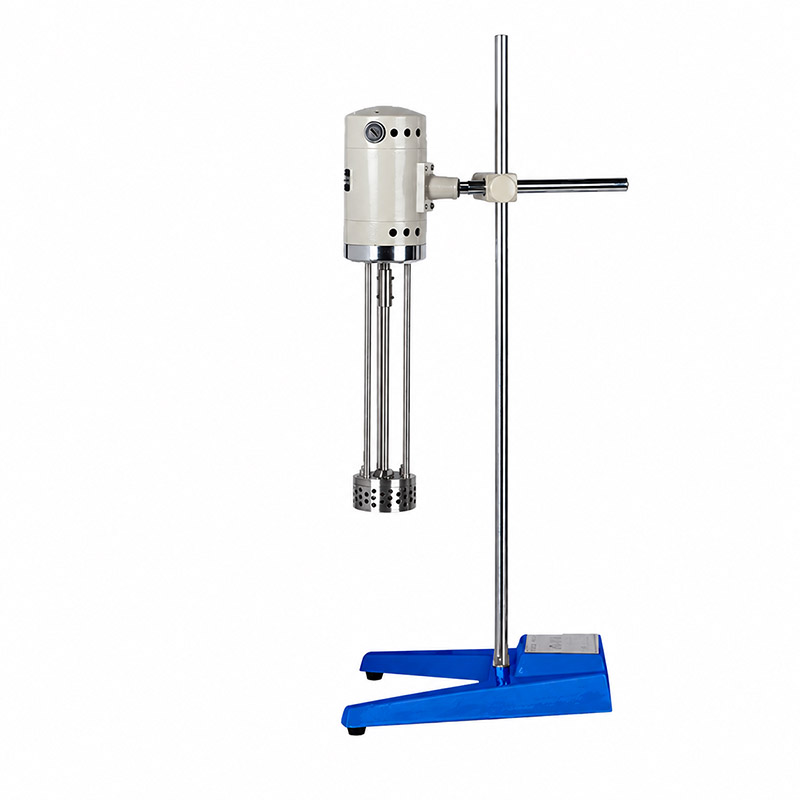
The laboratory shear emulsifier should be selected as a complete mixing system. The following checklist helps organize the technical questions before a purchase decision. It is written for laboratory and pilot work, where flexibility and reproducibility often matter more than maximum throughput.
- Working volume and vessel fit: Confirm the minimum and maximum batch size, the head immersion depth, and whether the vessel can be jacketed or covered.
- Rotor–stator geometry: Ask for the head type, slot or tooth pattern, clearance, and the intended viscosity range. These details explain more than motor power alone.
- Speed and torque: Check that the drive can deliver useful torque at the low speeds needed for viscous products, not only high speed for low-viscosity emulsions.
- Temperature control: Verify how temperature is measured and how heat is removed. A jacketed vessel is useful only if the heat-transfer area and coolant flow are adequate.
- Materials and seals: Confirm wetted materials, seal elastomer, and compatibility with the cleaning solvents as well as the product.
- Cleanability and access: Review how the head is removed, how the seal is accessed, and whether the internal passages can be inspected.
- Control and records: A unit that can log speed, time, and temperature makes process development more reliable, especially when several operators use the same equipment.
For final confirmation, review the shear emulsifier product page and discuss the intended formulation with TENCAN, the brand of Changsha Tianchuang Powder Technology Co., Ltd. The product page is the authoritative source for the available configuration, and the quotation should confirm the head, vessel, motor, and material options. A short trial with the actual formula is the best way to verify that the selected system can reach the target droplet size within the allowable temperature and time window.
When a Shear Emulsifier Is Not the Right Tool
A rotor–stator shear emulsifier is versatile, but it is not a universal homogenizer. If the target droplet size is below what a single-stage rotor–stator head can achieve, a high-pressure homogenizer or a different mechanical principle may be required. If the product is a dry powder blend, a shear emulsifier is irrelevant. If the main problem is solid particle size reduction, a mill is the appropriate equipment, not an emulsifier. If the formulation is extremely viscous and cannot be pumped to the head, a different mixing geometry may be needed before emulsification.
The decision should be based on the required droplet size, the allowable temperature rise, the number of batches, and the cleaning burden. A laboratory shear emulsifier can be an excellent development tool because it allows the formulator to study the effect of speed, time, and head geometry on a small scale. It can also support pilot work if the scale-up parameters are understood. It should not be selected solely because it is called a homogenizer or because it has a high maximum speed. The useful question is whether the complete system can deliver the required shear history to the entire batch within the constraints of the formulation.
Practical Next Steps for Lab Validation
Begin with a small batch that represents the formula and the addition sequence. Record the batch mass, head position, speed, time, and temperature at each stage. Take samples at several time points rather than only at the end, and measure droplet size distribution, viscosity, and visual stability. If the distribution stops changing, stop increasing the run time. If the temperature rises faster than expected, reduce the energy input or improve cooling before changing the formula.
Repeat the batch at least twice to establish process variability. A difference between duplicates is a warning that the procedure is not yet controlled. Check whether the same operator, the same head position, and the same addition rate were used. If the batch is sensitive to air, inspect for foam and consider a covered vessel or a slower initial speed. If the batch is sensitive to shear, reduce the number of passes and verify the key attribute after each change.
Finally, link the laboratory result to the intended scale. Decide whether tip speed, energy density, or residence time will be held constant, and document the rationale. Confirm that the larger system can remove heat and clean the head within the required changeover time. A shear emulsifier is most useful when it is treated as part of a defined process, not as a standalone high-speed mixer. With a controlled procedure and a clear understanding of the rotor–stator working zone, the equipment can help produce emulsions with a more predictable droplet size distribution and a more reliable stability profile.