

Product features
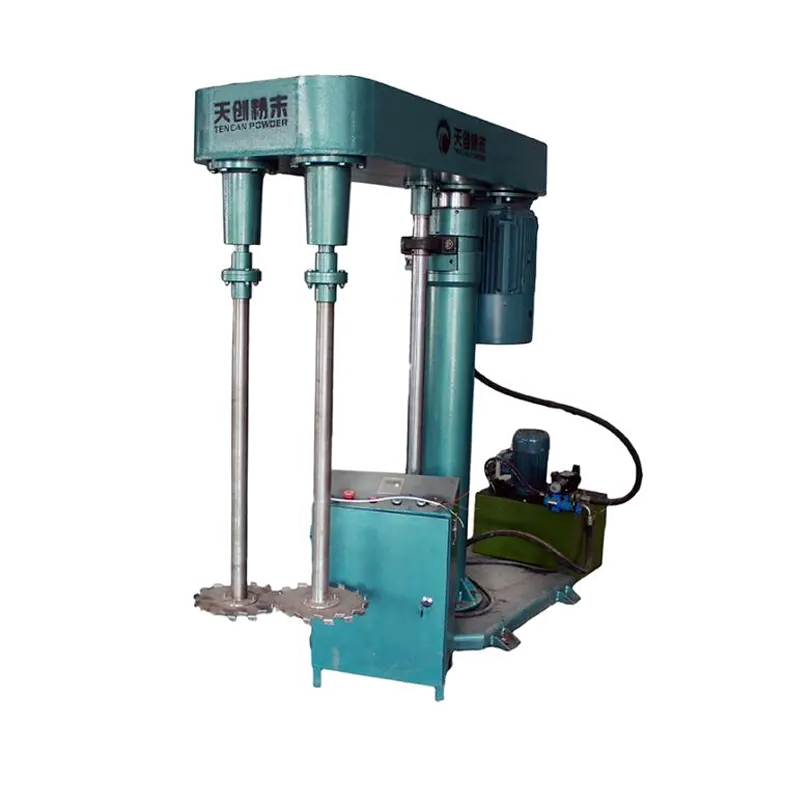
Dual-shaft arrangement
The two-shaft configuration provides the mixing and dispersing assembly, with actual head geometry confirmed for the chosen machine.
Hydraulic lifting
The lift positions the assembly relative to the batch vessel and assists access for loading, removal or cleaning.
Variable-speed operation
The source describes adjustable speed for matching the working action to the formulation and stage of processing.
Process-specific configuration
Select vessel, drive, lifting travel and electrical package around viscosity, batch size and the intended operating environment.
Applications
Coatings and pigments
Evaluate wet incorporation and dispersion of compatible colourants while checking the batch's flow and final application requirements.
Ink preparation
Compare formulations and operating conditions using suitable measurements of remaining agglomerates and sample uniformity.
Adhesive mixtures
Assess viscous formulations with the confirmed head arrangement, motor load and vessel dimensions taken into account.
Evaluating results
Whole-batch consistency
Sample several vessel positions and discharge portions to determine whether mixing and dispersion reach the complete charge.
Dispersion progress
Measure the relevant agglomerate or particle characteristics at defined intervals instead of assuming speed determines the result.
Heat and entrained air
Observe temperature and air incorporation while comparing operating settings for the actual formulation.
These are evaluation points for a sample trial, not measured results for a specific sample. Confirm performance under your actual operating conditions.
How it works
Set the working position
Secure a compatible vessel and position the dual-shaft assembly according to the selected equipment instructions.
Drive the formulation
The rotating elements move and shear the material, supporting mixing, dissolution or dispersion according to the configured heads.
Stop and evaluate
Stop before lifting or accessing the batch, then use measured results to refine the subsequent processing cycle.
Construction and configuration
Lift and guide structure
Check the specified travel, head clearance and vessel access as part of the installation plan.
Dual-shaft head assembly
Confirm the actual impellers or discs and whether their controls are independent; two shafts alone do not establish that capability.
Drive and electrical controls
Match load and supply requirements to the chosen system, and verify any specialised environmental protection separately.
Technical specifications
Compare the listed specifications and configurations. Scroll horizontally to view the complete table.
Specification table 1
| Model specifications | Host power (KW) | Maximum speed (r/min) | Dispersion disc diameter (mm) | Lifting stroke (mm) |
|---|---|---|---|---|
| FS-5.5 | 5.5 | 1400/2800 | 100-200 | 800 |
| FS-7.5 | 7.5 | 1400/2800 | 100-200 | 800 |
| FS-11 | 11 | 1400/2800 | 100-200 | 800 |
| FS-15 | 15 | 1400/2800 | 100-200 | 800 |
| FS-18.5 | 18.5 | 1400/2800 | 100-200 | 800 |
| FS-22 | 22 | 1400/2800 | 100-200 | 800 |
| FS-37 | 37 | 1400/2800 | 100-200 | 800 |
| FS-45 | 45 | 1400/2800 | 100-200 | 800 |
| FS-55 | 55 | 1400/2800 | 100-200 | 800 |
Confirm the selected model, power supply, contact materials and operating conditions before ordering. Performance depends on the material and process.