
Laboratory Rod Grinder: A Practical Guide
A sample that arrives at the laboratory as coarse crushed ore, clinker, slag, ceramic scrap, or soil rarely goes straight into analysis. It must be reduced to a size that is fine enough for the test but not so altered by overgrinding that the result is biased. A laboratory rod grinder fills a useful gap between coarse crushing and fine ball milling. Its long rods break particles along linear contacts rather than at isolated points, a different mechanical action that can produce a more controlled intermediate product in the right application. The useful question is not whether rod milling is universally better than ball milling, but whether the feed material, target size, and downstream method call for the breakage pattern that a rod charge provides.
What a Laboratory Rod Grinder Does in Sample Preparation
A laboratory rod grinder is a tumbling mill in which the grinding charge consists of metal rods rather than balls. As the drum rotates, the rods rise and then roll or cascade back into the charge. Because each rod presents a long contact line, breakage is concentrated on the coarsest particles that bridge the gaps between rods. This is the practical reason rod milling is often associated with relatively uniform size reduction and limited slime generation in coarse-to-intermediate grinding duties. The exact construction, drive arrangement, controls, and discharge design vary by model and should be checked against the manufacturer's product information.
The TENCAN laboratory rod grinder is intended for laboratory-scale work where a representative sample must be reduced under controlled conditions. In a typical test, a weighed feed sample is charged with the rods, the mill is run for a defined period, and the product is discharged, weighed, sampled, and screened or analyzed. The value of the machine lies less in a single headline number than in repeatability: the ability to apply a comparable breakage environment from one test to the next while changing one variable at a time.
A rod mill is not simply a ball mill filled with rods. Rod diameter, straightness, charge volume, feed size, and drum speed interact. If the rods are too light or poorly aligned, they may not deliver effective breakage; if the feed is too coarse for the drum and rod spacing, the charge can stall or the rods can become crossed. These are configuration and application questions, not reasons to force a rod mill into every sample preparation route.
Laboratory duties where a rod grinder may be considered include:
- preparing crushed mineral or ore samples for further grinding, leaching, flotation, or assay;
- reducing clinker, slag, or cement-related materials to an intermediate size;
- processing ceramic, glass, or other brittle raw materials where a controlled particle size distribution is useful;
- producing feed for a finer ball mill or pulverizer when direct fine grinding would create excessive fines;
- comparing breakage behavior or grindability under rod and ball charges.
These are application possibilities, not guarantees. Each material must be tested at the intended feed size and target size. The product page should be used to confirm the available drum size, drive, liner and rod options, and safety features for the specific laboratory.
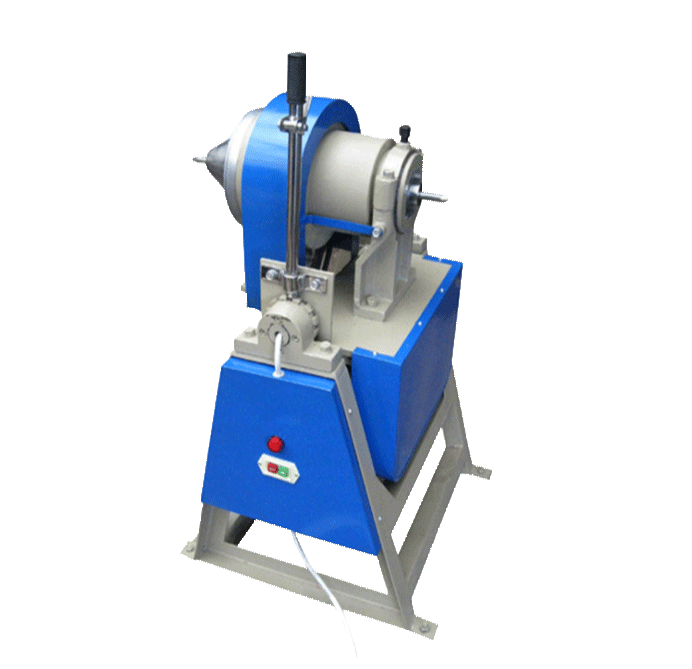
Laboratory rod grinder for controlled size reduction of prepared samples.
Rod Milling vs Ball Milling: Where the Breakage Mechanism Changes
Both machines are tumbling mills, but the media geometry changes how force is applied. A ball charge makes numerous point contacts as balls collide and roll. A rod charge makes line contacts, and the rods also tend to bridge across the charge. The result is a breakage environment that can favor the reduction of larger particles while leaving already fine material less exposed to repeated impact.
| Application factor | Rod milling tendency | Ball milling tendency |
|---|---|---|
| Media contact | Line contact along the rod length | Point contact at ball surfaces |
| Typical laboratory role | Coarse to intermediate reduction | Intermediate to fine grinding |
| Fines generation | Can be limited in suitable duties | Often higher during prolonged fine grinding |
| Product size distribution | Can be comparatively uniform | Depends strongly on media size and time |
| Contamination risk | Rod and liner wear must be managed | Ball and liner wear must be managed |
Line contact has consequences for liberation and downstream analysis. In an ore sample, breakage along grain boundaries or pre-existing cracks may expose mineral phases without reducing every particle to a powder. For a clinker or slag, a rod mill can prepare an intermediate product that is easier to control before a final fine-grinding step. For brittle ceramics or glass, the lower impact intensity may reduce the creation of very fine fragments, although this depends on the material's fracture behavior and the operating conditions.
None of this makes rod milling a universal substitute for ball milling. If the target is a fine powder, a ball mill, stirred mill, or pulverizer may be more appropriate. If the feed is already fine, the advantage of line contact becomes less relevant. The decision should be based on the feed size distribution, the target size, the acceptable level of fines, the required sample mass, and the risk of contamination.
Particle size distribution is often more informative than a single D50 value. A rod-milled product and a ball-milled product can have the same median size but different amounts of coarse and fine material. For a flotation test, excess fines may change froth behavior and reagent consumption. For a chemical assay, coarse particles may not dissolve completely. For X-ray diffraction or spectroscopy, the sample must be representative and sufficiently fine. A paired rod-versus-ball test, followed by sieving or laser diffraction, is usually more reliable than choosing a mill from a general rule.
Reading the Machine: Drum, Rods, Drive, and Discharge
From the outside, a laboratory rod grinder appears simple: a rotating drum, a support frame, a drive, and a control enclosure. The engineering detail is in how these parts interact. The drum must be stiff enough to resist deflection under the rod charge, the liners must protect the shell and help control the media motion, and the drive must deliver stable rotation without excessive vibration. A variable-frequency drive or controlled speed setting is useful when a test program needs to examine more than one operating condition.
The rod charge is the defining feature. Rods should be straight and reasonably uniform in diameter. A bent rod can disturb the charge motion, cross other rods, and create an uneven product. Rod length and diameter must suit the drum dimensions and the feed size. In laboratories that process different materials, dedicated rod sets or documented cleaning procedures help prevent cross-contamination. The correct rod material depends on the sample: steel is common for general work, but samples intended for trace-metal analysis may require a different liner and media combination, subject to the manufacturer's available options.
The discharge arrangement affects both recovery and cleaning. A laboratory mill may allow the entire batch to be discharged for weighing and sampling, or it may use a more controlled separation of product and media. Whatever the design, the operator should be able to recover the sample quantitatively and clean the drum without leaving retained material from the previous test. Dead zones around liners, end plates, and discharge openings deserve attention when a laboratory changes materials frequently.
The verified configuration for a specific purchase or test should come from the laboratory rod grinder product page, not from assumptions based on another mill. Drum volume, motor power, available liners, and control features are not interchangeable across models.
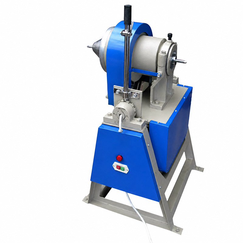
Laboratory rod grinder configuration for batch sample reduction.
Process Variables That Decide Rod Milling Performance
Once a rod mill is installed, the useful work begins with defining the test conditions. A single batch result is not a process; it is one point in a multivariate space. The variables below should be recorded and, where possible, controlled.
Feed Size and Preparation
The feed must be compatible with the drum, the rod charge, and the target reduction ratio. A rod mill performs best when it receives a prepared, reasonably consistent feed rather than a mixture containing both large lumps and already fine dust. Primary crushing or splitting before rod milling can reduce the risk of stalled charges and improve repeatability. At the same time, excessive pre-grinding removes the coarse particles that the rod charge is intended to break, making the later result less informative.
Feed preparation also affects sample representativeness. A coarse sample should be crushed and split by a suitable method before a small test charge is taken. If the sample is segregated, the mill may receive a non-representative fraction, and the final analysis may not describe the original lot. Record the feed size range, sample mass, and splitting method alongside the milling time.
Rod Charge and Media Condition
The rod charge controls the number and length of contact lines in the drum. Too little media reduces breakage opportunities; too much can overload the drive, reduce the free path of the charge, or make the mill difficult to start. Rod diameter should be selected in relation to the feed size and target product. Larger rods can handle coarser feeds but may leave more of the fine end under-treated; smaller rods increase contact frequency but may be less effective on coarse particles.
Rod condition matters as much as rod size. Worn rods become lighter and change the effective charge. Bent or crossed rods create inconsistent force transfer and can damage liners. Establish an inspection interval based on use, and replace rods as a set when wear or deformation becomes significant. For laboratories working with abrasive materials, the inspection interval may need to be shorter.
Mill Speed and Charge Motion
Drum speed controls whether the charge rolls, cascades, or is carried too high against the shell. Operating speed is usually described as a percentage of critical speed, the theoretical speed at which the outermost media would centrifuge. The appropriate range depends on drum diameter and media, so a speed setting from one mill should not be copied directly to another. Within the working range, higher speed generally increases energy input and breakage rate, but it can also increase wear, heat, and the risk of poor charge behavior.
Observe the mill during operation where the design permits, or use the manufacturer's guidance for safe observation. A stable, rhythmic charge motion is preferable to surging or violent impact. If the drive sounds labored or the frame vibrates abnormally, stop and check the charge, feed size, and rod condition before continuing.
Pulp Density, Dry Milling, and Material Transport
Wet milling can reduce dust, control temperature, and help transport material through the charge. The solids concentration must be high enough to provide particle contacts but low enough to avoid a viscous slurry that cushions the rods or retains material in the drum. The optimum depends on the material's density, particle size, clay content, and solubility. Water chemistry can also matter if the sample contains clays or salts that change slurry behavior.
Dry milling avoids adding a liquid that must later be removed, but it can generate dust, heat, and static. It may be preferable for water-sensitive materials or when the downstream test requires a dry powder. In either case, the mill should be charged and discharged using a procedure that prevents loss of fines and cross-contamination. For trace analysis, the cleaning method must be validated alongside the grinding method.
Grinding Time and Energy Input
Time is the easiest variable to change and the easiest to misinterpret. A longer run usually produces a finer product, but the relationship is not linear, and excessive time can cause overgrinding, heat buildup, and increased iron contamination. Two mills with different drum diameters, speeds, and media loads will not produce the same result at the same clock time. Where instrumentation allows, record motor load or energy consumption as well as time, because energy input is closer to the actual breakage work.
For a new material, run a small series of tests with increasing time and analyze the product after each interval. Stop when the target size and distribution are reached, not simply when the product looks fine. This approach gives the laboratory a defensible operating window rather than a single recipe that may fail when the feed changes.
Discharge, Classification, and Hold-Up
A batch mill retains the entire product until discharge, so hold-up and dead zones directly affect the result. Material trapped behind liners or in corners may be finer than the main product and can bias the next sample if cleaning is incomplete. A discharge procedure that recovers the full batch, including fines, improves mass balance and reproducibility. In continuous or semi-continuous configurations, classification after the mill can prevent already-fine particles from being overground, but the laboratory must confirm that the arrangement suits its sample size and test objective.
Matching the Laboratory Rod Grinder to Material and Test Objective
Material properties should drive the selection more than a generic preference for rod milling. Hard, brittle materials with a relatively coarse target may suit a rod charge, especially when the downstream test benefits from fewer fines. Tough or fibrous materials may deform rather than fracture and may require a different preparation method. Abrasive materials accelerate rod and liner wear, so maintenance and contamination control become part of the selection decision.
Moisture and clay content can make a dry rod mill difficult to discharge and can cause material to coat the rods and liners. In that case, wet milling or pre-drying may be more practical, provided the downstream method permits it. Heat-sensitive samples need attention to run time and energy input; a cool-down step or shorter intervals may be necessary. Samples intended for trace-element analysis require a careful review of liner and rod materials, because wear products can change the analytical result.
The target particle size is another boundary condition. A rod mill is well suited to intermediate reduction, but it is not the most efficient final-stage device for very fine powders. If the specification calls for a narrow fine fraction, a secondary ball mill, stirred mill, or jet mill may be needed. If the specification calls for a coarse product with minimal fines, rod milling may offer a better starting point. The laboratory should define both the target median size and the acceptable coarse and fine limits before choosing the mill.
A practical selection checklist includes:
- the feed size range and the mass required per test;
- the target size, particle size distribution, and downstream analytical method;
- material hardness, brittleness, moisture, and abrasiveness;
- acceptable contamination from rods, liners, and the drum;
- whether dry or wet processing is compatible with the sample and the laboratory;
- the need for repeatability, cleaning, and changeover between materials.
For a verified equipment reference, review the laboratory rod mill listing and confirm the available configuration with the manufacturer. A mill that is well matched to the sample mass and target size is more useful than a larger unit run below its effective charge.
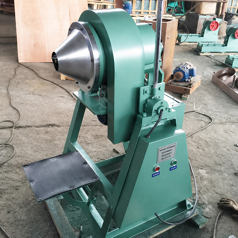
Laboratory rod grinder for evaluating material suitability and process conditions.
Troubleshooting Common Rod Mill Problems
Most rod milling problems show up as poor repeatability, unexpected fines, incomplete breakage, contamination, or mechanical noise. Begin with the sample and the charge before changing the machine. Record what was actually processed, not only the intended recipe.
Overgrinding and Excess Fines
If the product contains more fines than expected, check the grinding time, the feed size distribution, and the rod charge. A feed that is already fine may pass through the rod gaps and receive repeated treatment without the benefit of coarse-particle breakage. Reducing run time or using a coarser, better-prepared feed can help. In some cases, the target simply requires a different mill; forcing a rod mill to make a very fine product can increase wear and reduce control.
Inconsistent Product Size Distribution
Variation between batches can come from feed segregation, inconsistent sample mass, worn rods, changes in pulp density, or incomplete discharge. Weigh the feed and product, inspect the rods, and check the mill speed setting. If the sample is heterogeneous, improve splitting before milling. Run a replicate test with the same conditions to separate normal analytical variation from a process problem.
Rod Crossing, Stalling, or Abnormal Noise
Bent rods, oversized feed, an excessive charge, or a speed outside the intended range can cause rod crossing and unstable charge motion. Stop the mill, isolate the drive, and inspect the charge. Replace damaged rods and remove oversize material before restarting. Do not assume that a louder mill is grinding faster; abnormal noise often indicates inefficient impact or mechanical distress.
Contamination and Cleaning Losses
Iron contamination from steel rods and liners is a normal wear consideration, not a defect by itself. The question is whether the contamination is acceptable for the analysis. Use a documented cleaning procedure, run a blank or cleaning charge where appropriate, and check the mass balance. If trace elements are critical, discuss alternative liner and rod materials with the manufacturer rather than assuming that a standard configuration is suitable.
Scale-Up and Method Transfer
A laboratory rod mill result should not be scaled directly to a production mill by multiplying time or volume. Charge geometry, speed, media size, and discharge behavior change with scale. Use the laboratory test to establish the material's response and the relative ranking of conditions, then confirm the selected conditions in a pilot or production environment. Where power draw can be measured, compare energy input per unit mass rather than time alone.
A Practical Validation Sequence
Before routine use, establish a documented method: prepare and split the sample, record the feed size and mass, set the rod charge and speed, run a time series, discharge and weigh the full product, and analyze the particle size distribution. Repeat at least one condition to estimate method variability. Define cleaning and rod inspection intervals at the same time. This sequence produces a method that can be audited and transferred, which is more valuable than a single favorable result. Changsha Tianchuang Powder Technology Co., Ltd supplies laboratory grinding equipment under the TENCAN brand; final selection should be based on the confirmed product configuration and the laboratory's own material testing.